Wind turbine blade

A technology for wind turbines and blades, which is applied to wind turbines, wind turbines, engines and other directions that are consistent with the wind direction, can solve the problem that the blade profile is not provided with a flow guide device, etc., and achieves reduced production costs, simple shape, and simple mold part. Effect

Active Publication Date: 2012-05-16
LM GLASSFIBER
View PDF17 Cites 9 Cited by
  • Summary
  • Abstract
  • Description
  • Claims
  • Application Information

AI Technical Summary

Problems solved by technology

The profile of the blade is no

Method used


Image

  • Wind turbine blade
  • Wind turbine blade
  • Wind turbine blade

Examples


Embodiment Construction

[0152] figure 1 A conventional modern upwind wind turbine according to the so-called "Danish concept" is illustrated, having a tower 4, a nacelle 6 and a rotor with a substantially horizontal rotor shaft. The rotor comprises a hub 8 and three blades 10 extending radially from the hub 8 , each blade having a blade root 16 closest to the hub and a blade tip 14 furthest from the hub 8 . The rotor has a radius indicated by R.

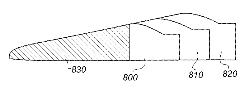
[0153] figure 2 A schematic view of a first embodiment of a wind turbine blade 10 according to the invention is shown. Wind turbine blade 10 has the shape of a conventional wind turbine blade and includes a root region 30 closest to the hub, a profile or airfoil region 34 furthest from the hub, and a transition region 32 between root region 30 and airfoil region 34 . The blade 10 comprises a leading edge 18 facing the direction of rotation of the blade 10 when the blade is mounted on the hub, and a trailing edge 20 facing in the opposite direction from ...


PUM


Abstract

A blade for a rotor of a wind turbine having a substantially horizontal rotor shaft is described. The rotor comprises a hub, from which the blade extends substantially in a radial direction when mounted to the hub. The blade comprises a profiled contour comprising a pressure side and a suction side as well as a leading edge and a trailing edge with a chord extending between the leading edge and the trailing edge, the profiled contour generating a lift when being impacted by an incident airflow, the profiled contour in the radial direction being divided into a root region with a substantially circular or elliptical profile closest to the hub, an airfoil region with a lift generating profile furthest away from the hub, and preferably a transition region between the root region and the airfoil region, the transition region having a profile gradually changing in the radial direction from the circular or elliptical profile of the root region to the lift generating profile of the airfoil region, wherein the airfoil region comprises at least a first longitudinal segment extending along at least 20% of a longitudinal extent of the airfoil region, the first longitudinal segment comprising a first base part having a leading edge and a trailing edge with a chord extending between the leading edge and the trailing edge. The first base part has an inner dimension that varies linearly in the radial direction of the blade in such a way that an induction factor of the first base part without flow altering devices at a rotor design point deviates from a target induction factor. The first longitudinal segment is provided with a number of first flow altering devices arranged so as to adjust the aerodynamic properties of the first longitudinal segment to substantially meet the target induction factor at the design point.

Description

technical field [0001] The invention relates to a blade for a wind turbine rotor having a substantially horizontal rotor shaft, said rotor comprising a hub from which said blade extends substantially in a radial direction when mounted on the hub, said The blade comprises a profiled contour comprising a pressure side and a suction side and a leading edge and a trailing edge with a chord extending between the leading edge and the trailing edge, the profiled contour When impacted by the incident air flow to generate lift, the profile is divided in the radial direction into the root region closest to the hub, the airfoil region furthest from the hub, and the root region and the wing Preferred transition regions between face regions, the root region having a substantially circular or elliptical profile, the airfoil region having a lift-generating profile, the transition region having a radially A profile with a gradual change in direction from the circular or elliptical shape of t...

Claims


Application Information

Patent Timeline
IPC IPC(8): F03D1/06
CPCF03D1/0675F05B2240/32Y02E10/72F03D1/0641F05B2240/301Y02E10/721F05B2240/305F05B2240/3062Y10T29/49336
Inventor P.富格尔桑格S.博夫L.富格尔桑格
Owner LM GLASSFIBER
Why Eureka
Try Eureka