
Swirl setting apparatus for a burner

A technology for burners and adjusting rods, which is applied in the direction of burners, gas fuel burners, and powder fuel burners, etc. It can solve the problems of divergence, flexible pipes cannot be controlled arbitrarily and accurately, and achieve space-saving and good cooling. Effect

Inactive Publication Date: 2012-05-16
UNITHERM CEMCON FEUERUNGSANLAGEN
View PDF4 Cites 1 Cited by
  • Summary
  • Abstract
  • Description
  • Claims
  • Application Information

AI Technical Summary

Problems solved by technology

However, the disadvantage of the construction known from EP 642 645 B1 is that the bending behavior of the flexible tube cannot be controlled arbitrarily precisely over its entire length in order to adjust the vortex, and above all it is also in this situation that the end of the flexible tube is due to The point of application of the pipe supports can only extend in a straight line and can sometimes stand upright, resulting in a diverging flow

Method used


Image

  • Swirl setting apparatus for a burner
  • Swirl setting apparatus for a burner
  • Swirl setting apparatus for a burner

Examples


Embodiment Construction

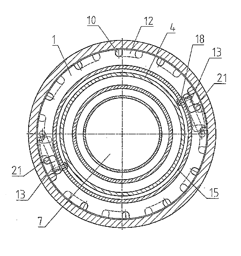
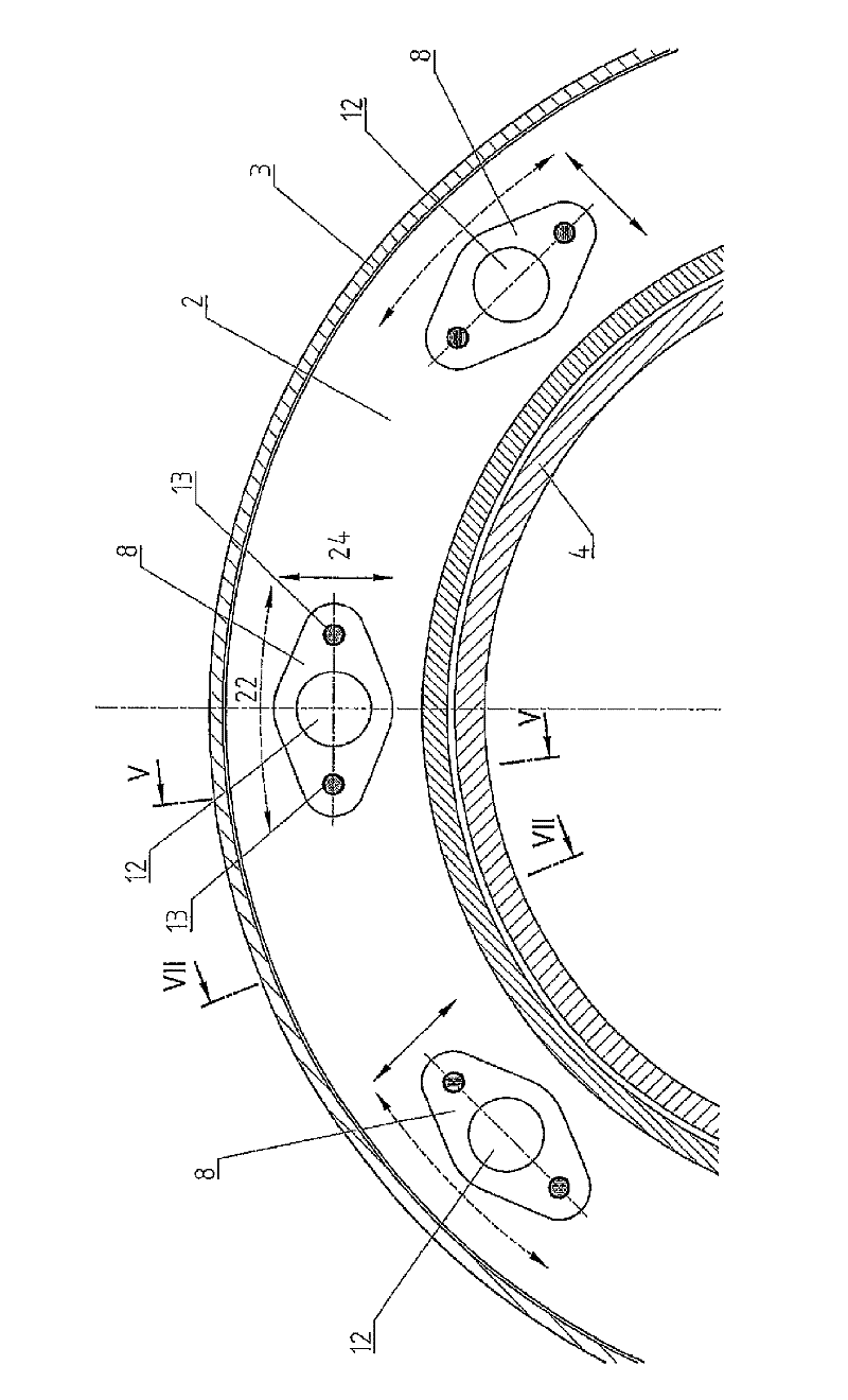
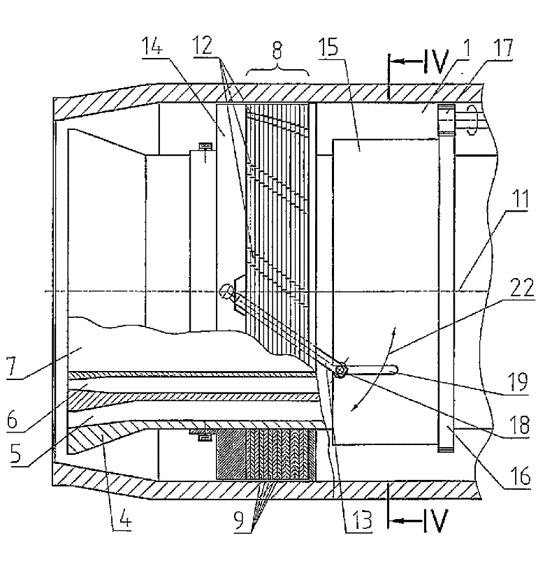
[0040] Such as figure 1 The flexible swirl adjustment shown is located in the annular primary air channel 1 at a distance from the burner outlet nozzle 2 . The primary air channel 1 is delimited here by the burner housing 3 and the cylindrical wall 4 . The other channels 5 , 6 and 7 for fuel are located inside the primary air channel 1 .

[0041] The swirl adjustment device arranged in the primary air channel 1 consists of a guide vane set 8 which is composed of a plurality of guide vanes 9 combined together. The baffle 9 generally has gaps 10 distributed on the circumference, and they are figure 1 and 2 The shown basic positions of the swirl adjustment devices are centered relative to each other, so that a straight course of the channel 12 results, parallel to the burner axis 11 . To adjust the swirl, there are adjusting levers 13 diametrically opposite each other with respect to the axis 11 , the ends of which face the burner nozzle 2 are rotatably mounted in a sealing p...


PUM


Abstract

In an apparatus for setting the outflow direction, in particular of a swirl, of air and / or burnable gas in a burner for the combustion of powdery or fine-grained, liquid and / or gaseous fuels, in particularly for rotary tubular kilns, comprising at least one primary air duct (1) and at least one jet nozzle (2), the primary air duct (1) has at least one disk set (8) comprising a plurality of parallel disks (9), wherein the disks (9) are mounted so they can be rotated about a common axis (11) and / or displaced relative to each other and in the main position have at least one first group of mutually aligned recesses (10), which together form a duct (12), wherein the duct (12) has a course that deviates from the main position, in particular an inclined and / or curved, particularly a helical course, when the disks (9); are successively rotated or displaced relative to each other compared to the main position. An adjusting apparatus is provided for rotating or displacing the disks (9).

Description

technical field [0001] The invention relates to a device for adjusting the outflow direction, in particular the swirl, of air and / or combustion gases in burners burning powdery or granular, liquid and / or gaseous fuels, in particular for converters, having At least one primary air passage and at least one combustion nozzle. [0002] The invention also relates to a further burner for burning pulverulent or granular, liquid and / or gaseous fuels, in particular for converters, having at least one primary air channel and at least one combustion nozzle. Background technique [0003] In order to influence the flame shape with primary air in converter burners, several burners are usually equipped with two primary air ducts. These air passages can be arranged coaxially outside the fuel passages or between the fuel passages. At least one oil spray gun is located in the center. Usually the nozzle cross section is designed to be adjustable from the cold end of the burner. The swirl a...

Claims


Application Information

Patent Timeline
Patent Type & Authority Applications(China)
IPC IPC(8): F23C7/00F23D1/00F23D14/24F23D11/38
CPCF23D1/00F23D11/383F23D2900/14241F23C7/008F23D17/00F23D14/48F23D14/24F23C7/006F23D2900/01001
Inventor H.莱德雷尔T.菲勒雷尔S.维茨曼A.莱德雷尔
Owner UNITHERM CEMCON FEUERUNGSANLAGEN
Learn More