Hybrid electrical vehicle

A hybrid vehicle, driving force technology, applied in hybrid vehicles, motor vehicles, electric vehicles, etc., can solve the problem of insufficient supply, and achieve the effect of ensuring cooling performance

Active Publication Date: 2012-05-23
HONDA MOTOR CO LTD
View PDF2 Cites 13 Cited by
  • Summary
  • Abstract
  • Description
  • Claims
  • Application Information

AI Technical Summary

Problems solved by technology

However, it is difficult to adequately lubricate / cool the motor and gearbox with this oil due to the spinning parts that are flung up and cannot provide enough oil

Method used


Image

  • Hybrid electrical vehicle
  • Hybrid electrical vehicle
  • Hybrid electrical vehicle

Examples


Embodiment Construction

[0018] The following is based on Figure 1 to Figure 3 Embodiments of the present invention will be described.

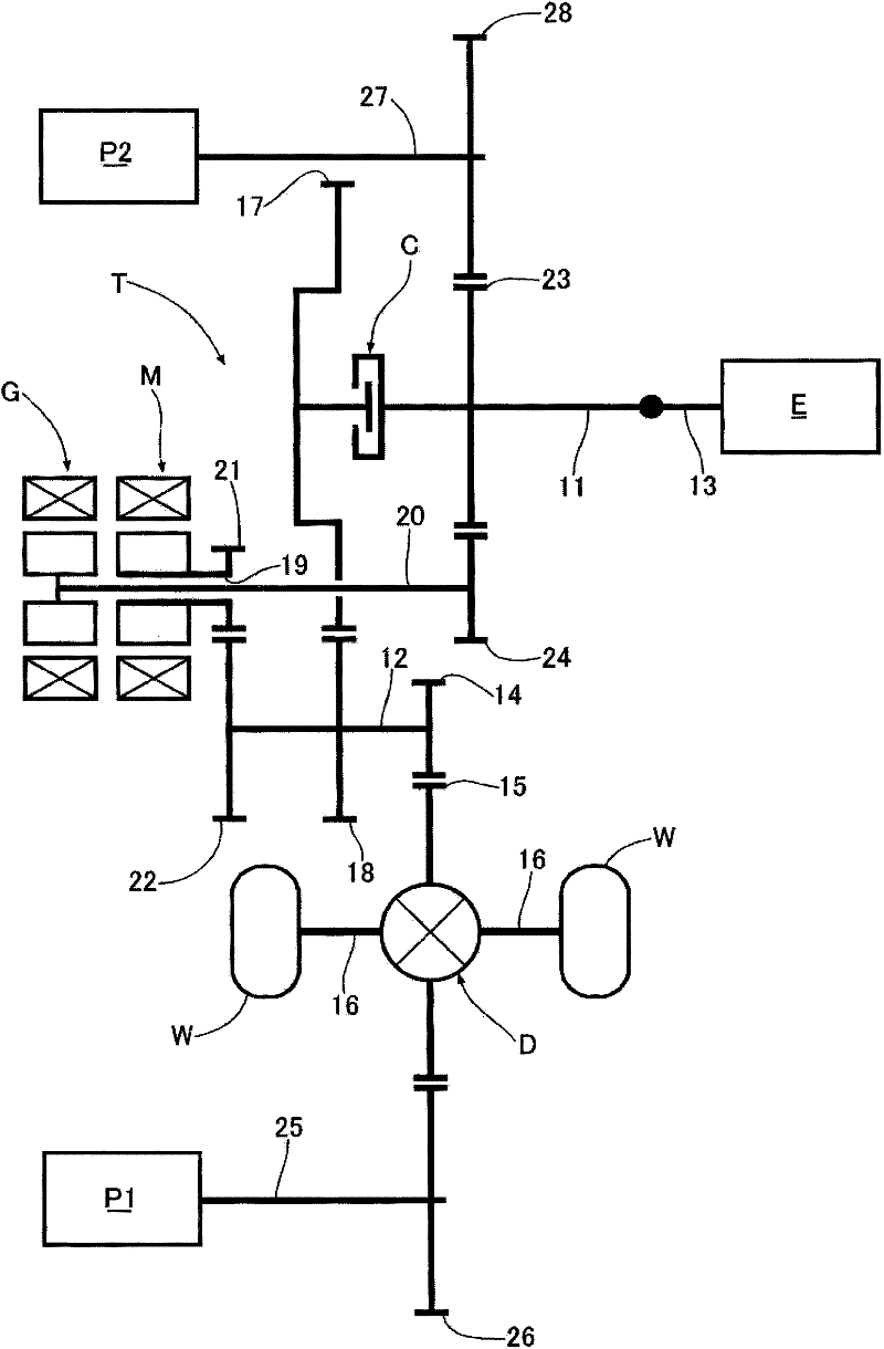
[0019] figure 1 It is a schematic diagram of a power transmission system of a hybrid vehicle, and a transmission T has an input shaft 11 and an output shaft 12 arranged in parallel. The crankshaft 13 of the engine E is connected in series to the input shaft 11 , and the output shaft 12 is connected to the left and right wheels W, W via the final driving gear 14 , the final driven gear 15 , the differential gear D and the left and right drive shafts 16 , 16 . A first driving gear 17 supported by the input shaft 11 via a clutch C meshes with a first driven gear 18 fixedly provided on the output shaft 12 .

[0020] The motor M and the generator G are arranged coaxially, and the generator shaft 20 is fitted relatively freely rotatably inside the hollow motor shaft 19 . The second driving gear 21 fixedly arranged on the motor shaft 19 meshes with the second driven gea...


PUM


Abstract

The invention provides a hybrid electrical vehicle which helps to effectively lubricating\cooling the lubricating\cooling portion or the motor of a hybrid electrical vehicle. The hybrid electrical vehicle is connected with wheels (W), and when the vehicle is running, the pumping output of a first petrol pump (P1) is increased along with the increase of the speed of the vehicle, that is, along with the increase of heat output of the lubricating\cooling portion, the motor (M) and the like, such that enough needed petrol can be automatically provided to the lubricating\cooling portion for guarantee of cooling performance. In addition, when the vehicle stops and the first petrol pump (P1) stops, if a second petrol pump (P2) is driven via an engine (E), petrol can be provided to the motor (M), the lubricating\cooling portion and the like without barrier under a high-temperature state. Moreover, lubricating\cooling oil channels extended from the first petrol pump and the second petrol pump are mutually communicated, such that even if one of the two petrol pumps stops running, all lubricating\cooling portions can be cooled, and the air is not liable to be absorbed into a lubricating\cooling oil channel that is communicated with a petrol pump on a stopping side.

Description

technical field [0001] The present invention relates to a hybrid vehicle capable of traveling with the driving force of an electric motor and an engine. Background technique [0002] In a vehicle that transmits the driving force of the engine to the wheels via a forward / reverse switching mechanism, a continuously variable transmission, and a final reducer, the oil pumped by the engine-driven oil pump is used for lubrication and cooling when running with the engine, and when the engine is stopped On the other hand, when traveling by traction, the oil thrown up by the rotating member of the final reducer is guided to the forward / reverse switching mechanism, and the forward / reverse switching mechanism is lubricated and cooled. These contents are known in the following patent document 1. [0003] [Patent Document 1] Japanese Patent No. 3785857 [0004] In addition, in a hybrid vehicle using an engine and an electric motor as driving sources for travel, as in a vehicle using an ...

Claims


Application Information

Patent Timeline
Patent Type & Authority Applications(China)
IPC IPC(8): B60R17/00B60K6/36B60L50/16
CPCY02T10/6234Y02T10/7077Y02T10/62Y02T10/7072
Inventor 武井宽高桥徹本永豊明
Owner HONDA MOTOR CO LTD
Why Eureka
Try Eureka