Battery cooling structure

A cooling structure and storage battery technology, applied in the combination of power plant cooling layout, secondary battery, battery temperature control, etc., can solve the problems of the cooling effect of the third battery module, such as decreased cooling effect, and achieve improved cooling effect and large heat transfer area Effect

Inactive Publication Date: 2012-05-23
HONDA MOTOR CO LTD
View PDF4 Cites 4 Cited by
  • Summary
  • Abstract
  • Description
  • Claims
  • Application Information

AI Technical Summary

Problems solved by technology

At this time, if the newly added second air intake passage is arranged adjacent to the first exhaust passage or the second exhaust passage, the heat-exchanged air flowing in the first exhaust passage or the second exhaust passage and the Heat exchange is performed between the pre-heat-exchange air flowing in the second intake passage, so that the temperature of the air flowing in the second intake passage rises and the cooling effect of the third battery module may decrease

Method used


Image

  • Battery cooling structure
  • Battery cooling structure
  • Battery cooling structure

Examples


Embodiment Construction

[0038] Below, based on Figure 1 to Figure 13 , to describe the embodiment of the present invention.

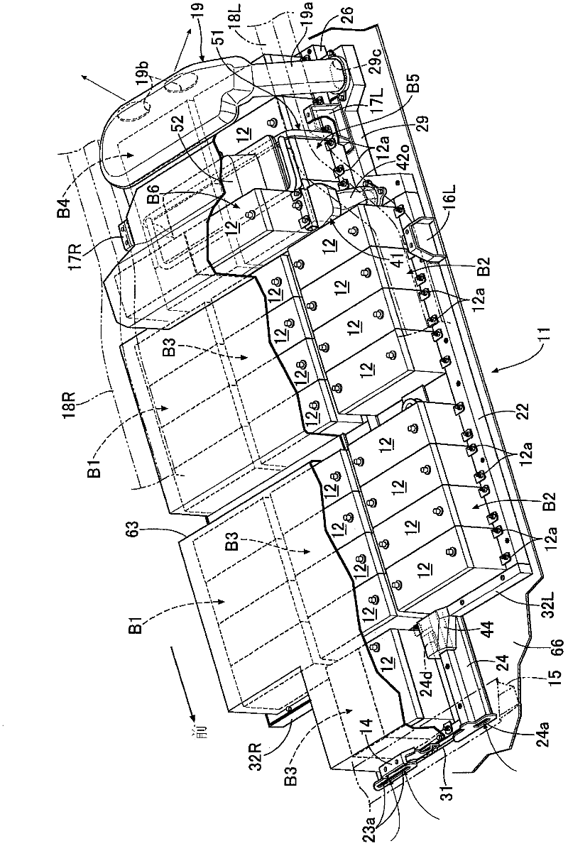
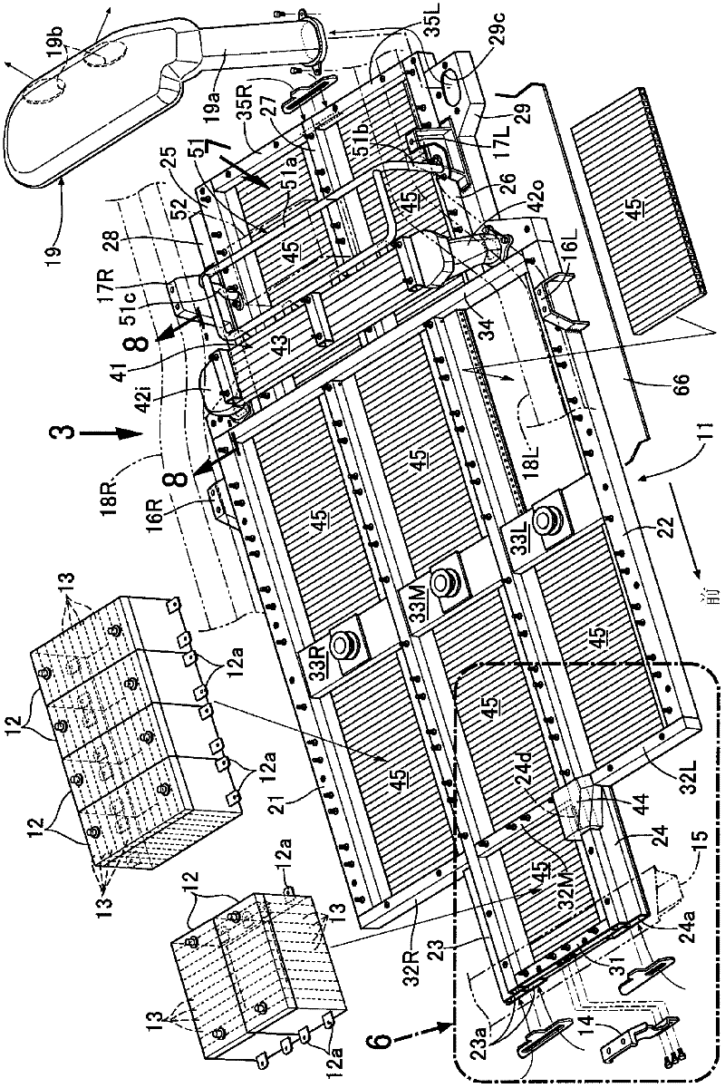
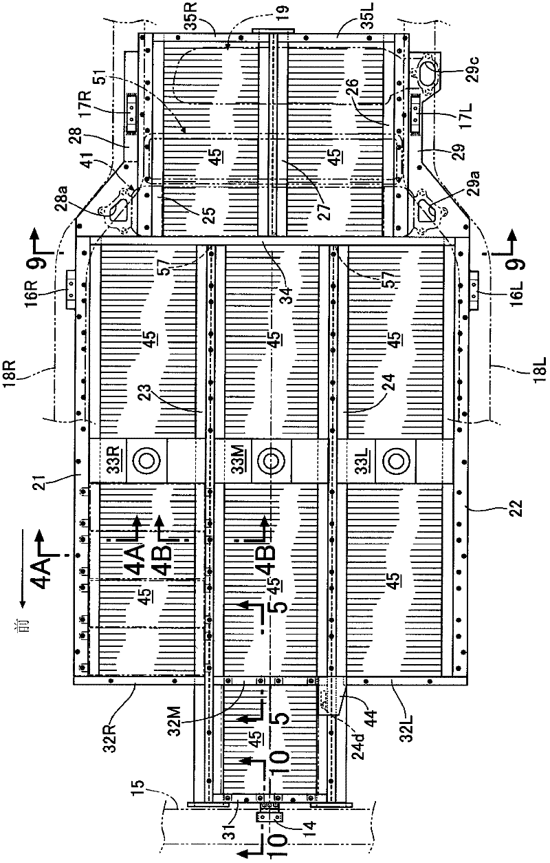
[0039] Such as Figure 1 ~ Figure 3 As shown, a battery unit for supplying electric power to a motor generator serving as a driving power source of an electric vehicle includes a flat disk 11 and a plurality of battery modules 12 . . . placed on the surface of the disk 11 . Each battery module 12 has a rectangular parallelepiped shape, and accommodates a plurality of battery cells 13 electrically connected in series inside it (refer to figure 2 ). Two brackets 12 a , 12 a for fixing the battery module 12 to the tray 11 protrude from both ends in the longitudinal direction of the battery module 12 .

[0040] The mounting bracket 14 provided at the front of the panel 11 is combined with the cross member 15 of the vehicle body, and the two mounting brackets 16L, 17L provided at the left rear of the panel 11 are combined with the left side frame 18L. Two mounting brackets 16...


PUM


Abstract

A battery cooling structure includes a first battery group, a second battery group, a third battery group, a first duct, a second duct, a third duct, a fourth duct, a fifth duct, a first connecting duct, a second connecting duct, a third connecting duct, and a bypass duct. The first duct is configured to allow a cooling medium after heat exchange to flow through the first duct. The second duct is configured to allow a cooling medium after heat exchange to flow through the second duct. The fifth duct is configured to allow a cooling medium after heat exchange to flow through the fifth duct. The bypass duct connects the fifth duct to the second duct or to the first duct.

Description

technical field [0001] The present invention relates to a battery cooling structure for cooling a battery mounted on an electric vehicle or a hybrid vehicle. Background technique [0002] The following Patent Document 1 describes as a second embodiment a structure in which first and second exhaust passages are provided on the left and right sides of an air intake passage (first air intake passage) provided in the center, and The first battery module is arranged between the air intake duct and the first exhaust duct, and the second battery module is arranged between the air intake duct and the second exhaust duct, so that the air supplied from the air intake duct is branched to the left and right to the first battery module. 1. The second battery module is cooled, and the air whose temperature has been raised due to heat exchange is discharged from the first and second exhaust passages. [0003] [Patent Document 1] Japanese Patent Laid-Open No. 2010-15931 [0004] However, ...

Claims


Application Information

Patent Timeline
Patent Type & Authority Applications(China)
IPC IPC(8): H01M10/50B60K11/00B60K1/04B60K11/06H01M10/60H01M10/613H01M10/617H01M10/625H01M10/6563
CPCY02E60/12B60K1/04H01M10/5057H01M10/5059H01M10/5004B60K2001/005H01M10/5016H01M10/5053H01M10/613H01M10/625H01M10/6554H01M10/6556H01M10/6557Y02E60/10
Inventor 片山吾一山本康一木村有寿
Owner HONDA MOTOR CO LTD
Why Eureka
Try Eureka