Wire rod plugging structure

A plug-in structure and wire technology, applied in the direction of fixed/insulated contact components, connections, contact parts, etc., can solve the problems of poor conduction, narrow width, small spacing, etc., and achieve the effect of simple operation, labor saving, and simple structure

Active Publication Date: 2015-01-07
ADVANCED FLEXIBLE CIRCUITS
View PDF9 Cites 0 Cited by
  • Summary
  • Abstract
  • Description
  • Claims
  • Application Information

AI Technical Summary

Problems solved by technology

[0004] In the actual application of the known connector products, the internal slots are provided with a plurality of metal guides for the corresponding contact of a plurality of wires of the flat cable. and volume, so the distance between each metal lead in the connector becomes very small, and the width of the wire contact position of each metal lead is also very narrow. When the size and width of the conductive contact section of the metal conductor are close to or greater than the width of the wire contact position of the metal lead, as long as the connector and the flat cable are slightly offset, it is possible to make the conductive contact section of each wire Dislocation contact with the wire contact position of each metal lead in the connector, resulting in poor conduction or short circuit during signal transmission

Method used


Image

  • Wire rod plugging structure
  • Wire rod plugging structure
  • Wire rod plugging structure

Examples


specific Embodiment approach

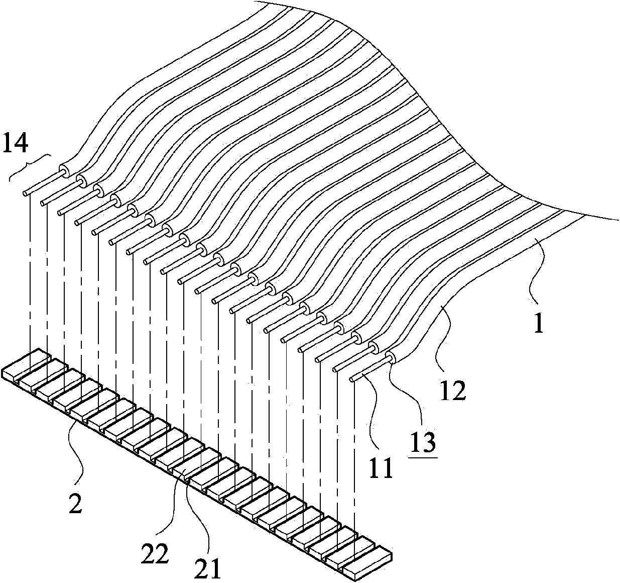
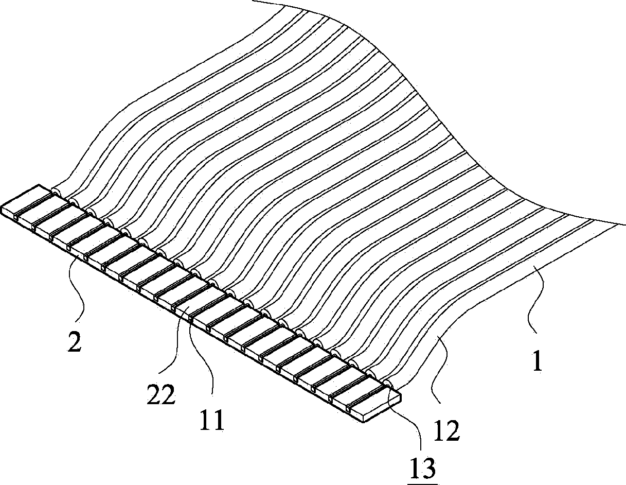
[0046] see also figure 1 and figure 2 as shown, figure 1 shows an exploded perspective view of the first embodiment of the present invention, figure 2 A perspective view of a first embodiment of the invention is shown. The wire plug-in structure of the present invention includes a plurality of wires 1 extending parallel to each other, wherein the wires 1 can be arranged in close proximity to each other, or each wire 1 can be separated from each other, and each wire 1 has a wire 11 and an insulating layer 12 covering the wire 11. As shown in the figure, one end of the wire 1 is defined as a plug-in end 13 , and the wire 11 protruding from the plug-in end 13 is defined as a conductive contact section 14 .

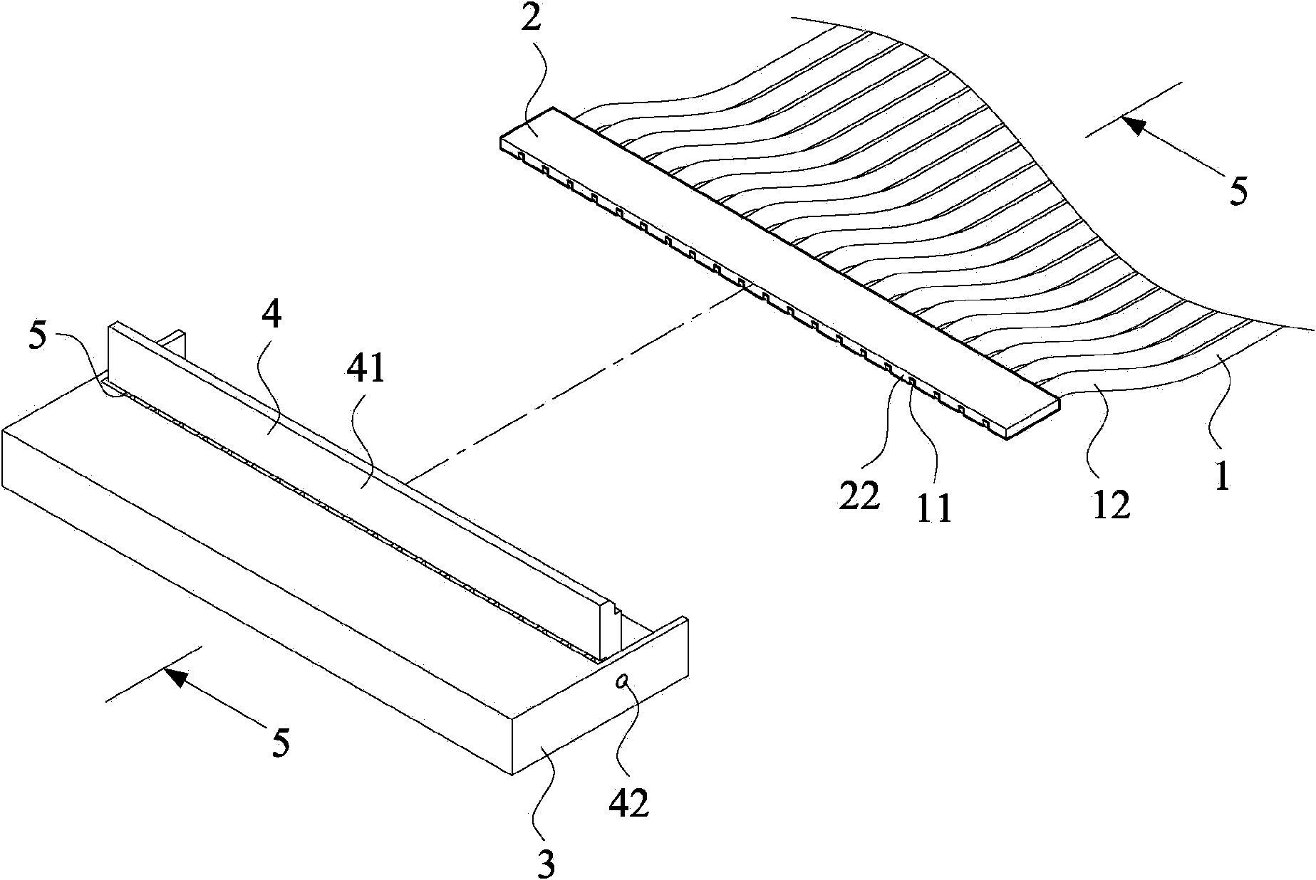
[0047] In this embodiment, the plug-in end 13 of the wire 1 is combined with a plug-in auxiliary unit 2. The plug-in auxiliary unit 2 includes a plurality of positioning grooves 21, and each positioning groove 21 extends parallel to each other and is arranged on the plu...


PUM


Abstract

The invention provides a wire rod plugging structure, which comprises a plurality of parallelly-extending wire rods, wherein each wire rod is provided with a conducting wire and an insulating layer coated on the conducting wire; one end of the wire rod is defined as a plugging end, and the conducting wire protruding out of the plugging end is defined as a conductive contact section; a plugging auxiliary unit is combined to the plugging end of the wire rod, and comprises a plurality of positioning slots; all the positioning slots parallelly extend with one another, are arranged on one surface of the plugging auxiliary unit, and are separated from one another through an insulating part; the conductive contact section of each conducting wire is positioned in the positioning slot respectively; and when the plugging end of the wire rod and the plugging auxiliary unit are plugged into a corresponding connector slot, the conductive contact section of each conducting wire of the wire rods correspondingly contacts a metal conducting piece of the connector slot respectively. By using the wire rod plugging structure, a connector can be well connected with a flat cable which has a plurality of wire rods so as to overcome the defects of known wire rods during plugging application.

Description

technical field [0001] The invention relates to a plug-in structure, in particular to a wire plug-in structure plugged into a connector. Background technique [0002] In the circuit design of various electrical equipment, electronic equipment, computer equipment and communication equipment, signal connectors are often used for signal transmission. Due to the demand of lightness, thinness and shortness, whether it is an electronic component or a signal line, its size and volume need to be reduced accordingly. In terms of the technological evolution of signal lines, flat cables have become a product commonly used in various electronic products. In terms of the types of cables, there are flexible circuit boards made by the technology of flexible circuit boards, and there are also flexible flat cables (FFC) formed by using a plurality of wires closely connected to each other. [0003] When a flat cable with multiple wires is used as a signal transmission line in practical appl...

Claims


Application Information

Patent Timeline
Patent Type & Authority Patents(China)
IPC IPC(8): H01R12/77H01R12/88H01R13/02H01R13/40H01R13/46
Inventor 林崑津苏国富卓志恒
Owner ADVANCED FLEXIBLE CIRCUITS
Why Eureka
Try Eureka