Controller device and control method of new energy power-supply system

A power supply system and controller technology, applied in the direction of circuit devices, battery circuit devices, collectors, etc., can solve the problems of low power utilization rate and low conversion efficiency of controllers, so as to improve the utilization rate, overcome the low power utilization rate, Effect of improving conversion efficiency

Active Publication Date: 2012-05-23
ZTE CORP
View PDF6 Cites 14 Cited by
  • Summary
  • Abstract
  • Description
  • Claims
  • Application Information

AI Technical Summary

Problems solved by technology

[0008] The technical problem to be solved by the present invention is to provide a controller device of a new energy power supply system and its control method, which are used to overcome the problems of low power utilization rate and low conversion efficiency of the controller existing in the DC source of the new energy in the prior art defect

Method used


Image

  • Controller device and control method of new energy power-supply system
  • Controller device and control method of new energy power-supply system
  • Controller device and control method of new energy power-supply system

Examples


Embodiment 1

[0072] Embodiment 1: A controller device and control method for a solar photovoltaic power supply system

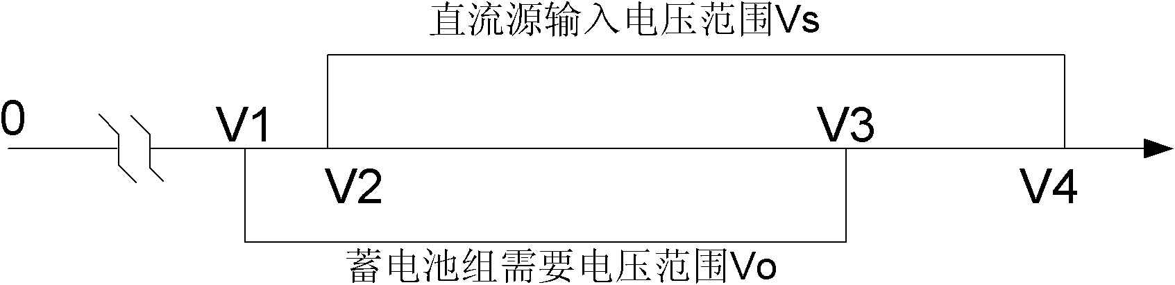
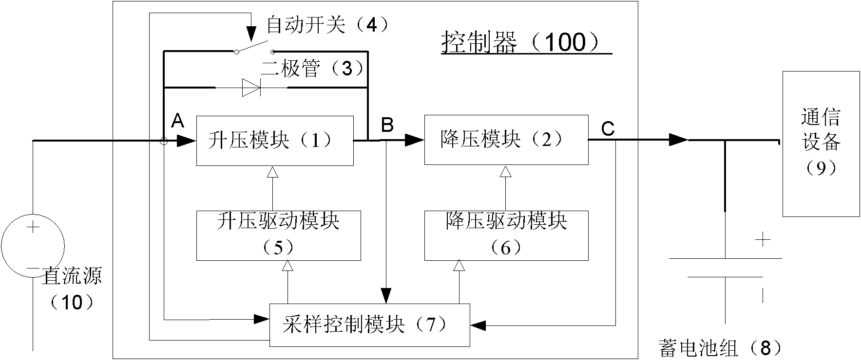
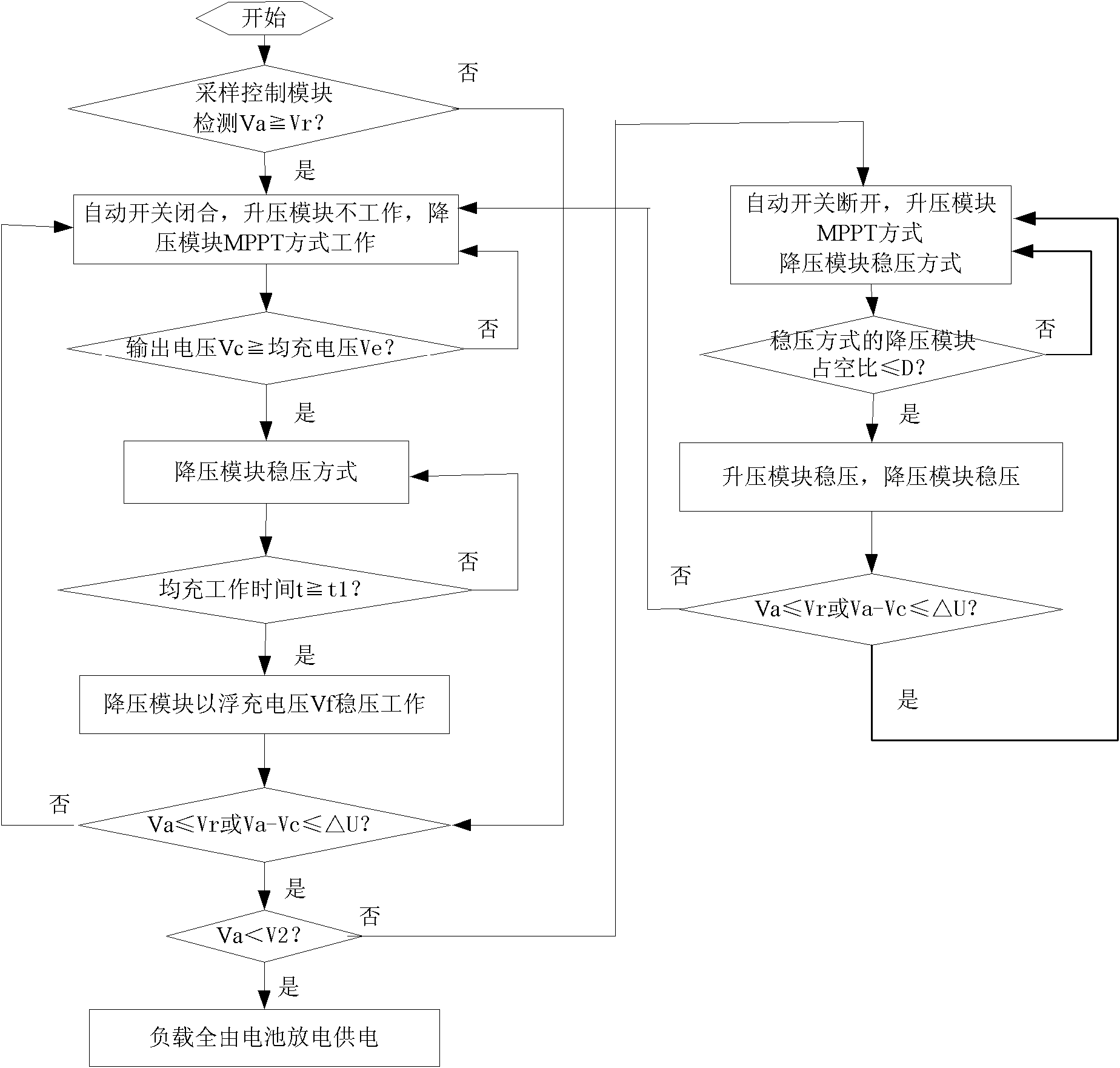
[0073] Such as Figure 4 As shown, a schematic diagram of the controller device based on the solar photovoltaic power supply system of the present invention is given. In this example, the figure 2 The shown DC source 10 is replaced by a solar photovoltaic array 200, and the solar photovoltaic array 200 is used as a DC source to supply power to the load of the communication equipment and charge the storage battery through the controller.

[0074] In order to be compatible with the component output voltage of the previous drop-in solar power supply system, and also to be compatible with the 48V battery pack, in the first embodiment, one or more sets of two standard PV modules (English photovoltaic module, photovoltaic module) in parallel are used ) solar array in series as a DC source, and a standard PV module contains 72 Cells (primary battery units) connected in series...

Embodiment 2

[0102] Embodiment 2: A controller device and control method for a wind energy power supply system

[0103] Such as Figure 5 The shown embodiment two and Figure 4 The technical solutions of the first embodiment shown are basically the same, the difference is that compared with the solar photovoltaic array 200 as the DC source, the second embodiment uses the wind power generation system 300 as the power source, and the wind power generation generally outputs alternating current. Before the input terminal of the controller 100, a rectification module 11 is added, and the power generated by the fan is rectified by the rectification module and converted into direct current.

[0104] The structure and control method of the subsequent controller device 100 are similar to those of the controller device and control method in Embodiment 1.

[0105] Embodiment 2 Since the fan is used to generate electricity as the DC source, the utilization rate of wind energy and the conversion effi...


PUM


Abstract

The invention discloses a controller device and a control method of a new energy power-supply system; the controller device comprises a boost module (1), a voltage reduction module (2), a diode (3), an automatic switch (4), a boost driving module (5), a voltage reduction driving module (6) and a sampling control module (7), wherein the sampling control module (7) is used for sampling voltage signals and current signals respectively from an input point (A) and an output point (B) of the boost module (1) as well as an output point (C) of the voltage reduction module, and after processing and operation, the sampled voltage signals and current signals are sent into the boost driving module (5) and the voltage reduction driving module (6), so that the automatic switch (4) can be controlled to be switched on or off; when the input voltage Va of the input point (A) of the boost module (1) is lower than the set value Vr, the input voltage is boosted; and when the input voltage Va is higher than the set value Vr, the controller device is shut down and stops working. The invention is capable of improving the utilization rate of a direct current (DC) source and the conversion efficiency, and is compatible with an input withdrawal type DC source.

Description

technical field [0001] The invention relates to the technical field of new energy power supply systems, in particular to a controller device and a control method for a new energy power supply system. Background technique [0002] Under the pressure of energy saving and emission reduction, communication equipment uses new energy systems such as solar energy and wind energy as power supply systems more and more. The power provided by the new energy power supply system to communication equipment is DC input or can be rectified into DC input. Hereinafter, the DC power generated by new energy is referred to as "DC source". When the DC source is within the acceptable voltage range, the controller charges the battery pack with a nominal voltage of 48V or 24V or 12V, and at the same time supplies power to the communication equipment load. When the voltage range of the DC source exceeds the acceptable range of the controller or the DC source When it is not enough to support the load...

Claims


Application Information

Patent Timeline
Patent Type & Authority Applications(China)
IPC IPC(8): H02M3/16H02J7/00
Inventor 谢凤华武士越范俊宁马廉攀王恰
Owner ZTE CORP
Why Eureka
Try Eureka