Unlock instant, AI-driven research and patent intelligence for your innovation.

Digital delay line circuit and delay locked loop circuit

A digital delay line and delay-locked loop technology, applied in the direction of electrical components, automatic power control, etc., can solve the problems of large chip area and power consumption, poor delay line jitter performance, and insufficient delay line phase accuracy.

Inactive Publication Date: 2012-05-23
ANYKA (GUANGZHOU) MICROELECTRONICS TECH CO LTD
View PDF3 Cites 5 Cited by
  • Summary
  • Abstract
  • Description
  • Claims
  • Application Information

AI Technical Summary

Problems solved by technology

[0010] The purpose of the embodiment of the present invention is to provide a digital delay line circuit, aiming to solve the problems that the phase accuracy provided by the delay line is not high enough, it needs to consume a large chip area and power consumption, and the jitter performance of each stage of the delay line is poor.

Method used


Image

  • Digital delay line circuit and delay locked loop circuit
  • Digital delay line circuit and delay locked loop circuit
  • Digital delay line circuit and delay locked loop circuit

Examples


Embodiment Construction

[0017] In order to make the object, technical solution and advantages of the present invention clearer, the present invention will be further described in detail below in conjunction with the accompanying drawings and embodiments. It should be understood that the specific embodiments described here are only used to explain the present invention, not to limit the present invention.

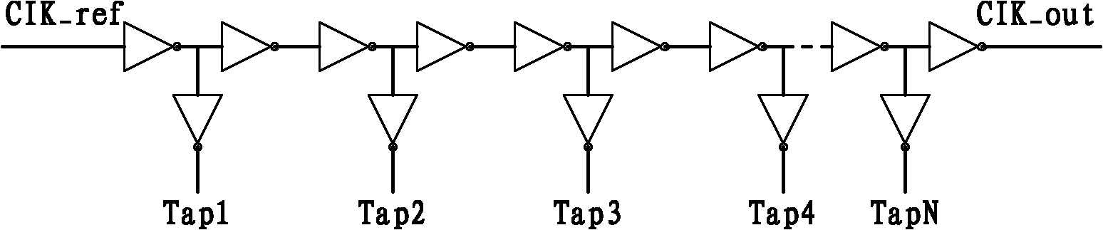
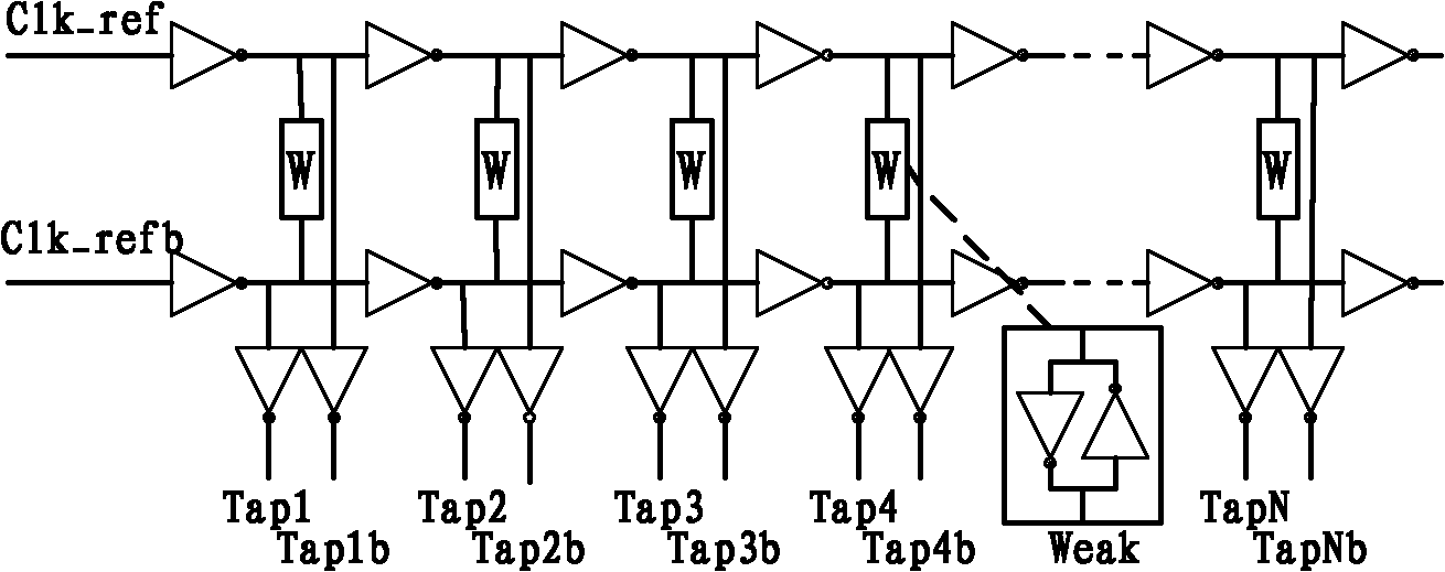
[0018] The digital delay line circuit in the embodiment of the present invention is composed of a pair of complementary digital delay line circuits, each delay line circuit includes a delay line, and the two delay lines are coupled through a latch unit, each The delay line consists of a series of connected inverters.

[0019] The embodiment of the present invention provides a digital delay line circuit. The digital delay line circuit is composed of a pair of complementary digital delay line circuits. Each delay line circuit includes a delay line. The latch unit is coupled, and each delay line is f...


PUM


Abstract

The invention is applied to the field of digital circuits, and provides a digital delay line circuit and a delay locked loop circuit. The digital delay line circuit consists of a pair of complementary digital delay line circuits; each digital delay line circuit comprises a delay line; two delay lines are coupled through a latch; each delay line is formed by connecting a series of inverters; and the two delay lines takes two complementary signals as input clock signals. A pair of complementary digital delay line circuits is adopted, and the two delay lines are coupled through a latch unit; the complementary digital delay lines can provide phase accuracy which is equal to the delay time of an inverter and doubled than the accuracy of the common delay line, and an actual high speed application requirement can be greatly met.

Description

technical field [0001] The invention belongs to the field of digital circuits, in particular to a digital delay line circuit and a delay phase-locked loop circuit. Background technique [0002] With the continuous improvement of the read and write speed of the memory system, the timing requirements for the clock frequency are also getting higher and higher. Therefore, delay-locked loops are more and more widely used in such high-speed CMOS interface circuits. Delay-locked loops can be divided into two categories: analog delay-locked loops and digital delay-locked loops. The analog delay-locked loop has a relatively good power supply rejection ratio, can provide good jitter performance, and high phase accuracy. However, the structure of the analog delay-locked loop circuit is complex, and there are certain design difficulties and uncertainties. The circuit structure of the digital delay-locked loop is relatively simple, easy to implement, and requires a relatively low oper...

Claims


Application Information

Patent Timeline
IPC IPC(8): H03L7/06
Inventor 梁仁光胡胜发
Owner ANYKA (GUANGZHOU) MICROELECTRONICS TECH CO LTD
Features
  • R&D
  • Intellectual Property
  • Life Sciences
  • Materials
  • Tech Scout
  • Unparalleled Data Quality
  • Higher Quality Content
  • 60% Fewer Hallucinations
Learn More