Eureka AIR delivers breakthrough ideas for toughest innovation challenges, trusted by R&D personnel around the world.

Light-emitting diode (LED) driving circuit

A LED drive and circuit technology, applied in the direction of lamp circuit layout, electric light source, lighting device, etc., can solve the problems of high-frequency interference, high cost, easy damage, etc.

Inactive Publication Date: 2012-05-23
OCEANS KING LIGHTING SCI&TECH CO LTD +1
View PDF2 Cites 10 Cited by
  • Summary
  • Abstract
  • Description
  • Claims
  • Application Information

AI Technical Summary

Problems solved by technology

[0003] At present, DC-DC chopping technology is used to drive LED in low-voltage places. It has the advantages of low power consumption, high efficiency, stability and reliability, small size per unit power, light weight, etc., but its cost is high, the circuit is complicated, and easy to use. Damage, strong high-frequency interference and other shortcomings, which bring inconvenience to users

Method used


Image

  • Light-emitting diode (LED) driving circuit
  • Light-emitting diode (LED) driving circuit
  • Light-emitting diode (LED) driving circuit

Examples


Embodiment Construction

[0020] The specific implementation manners of the present invention will be described in detail below in conjunction with the accompanying drawings.

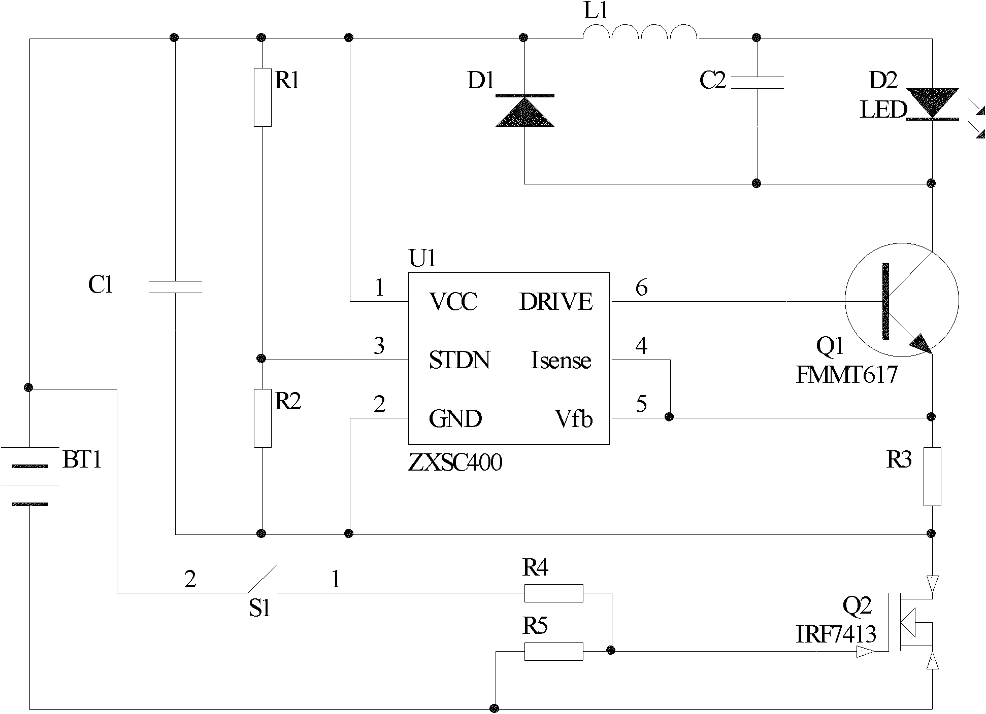
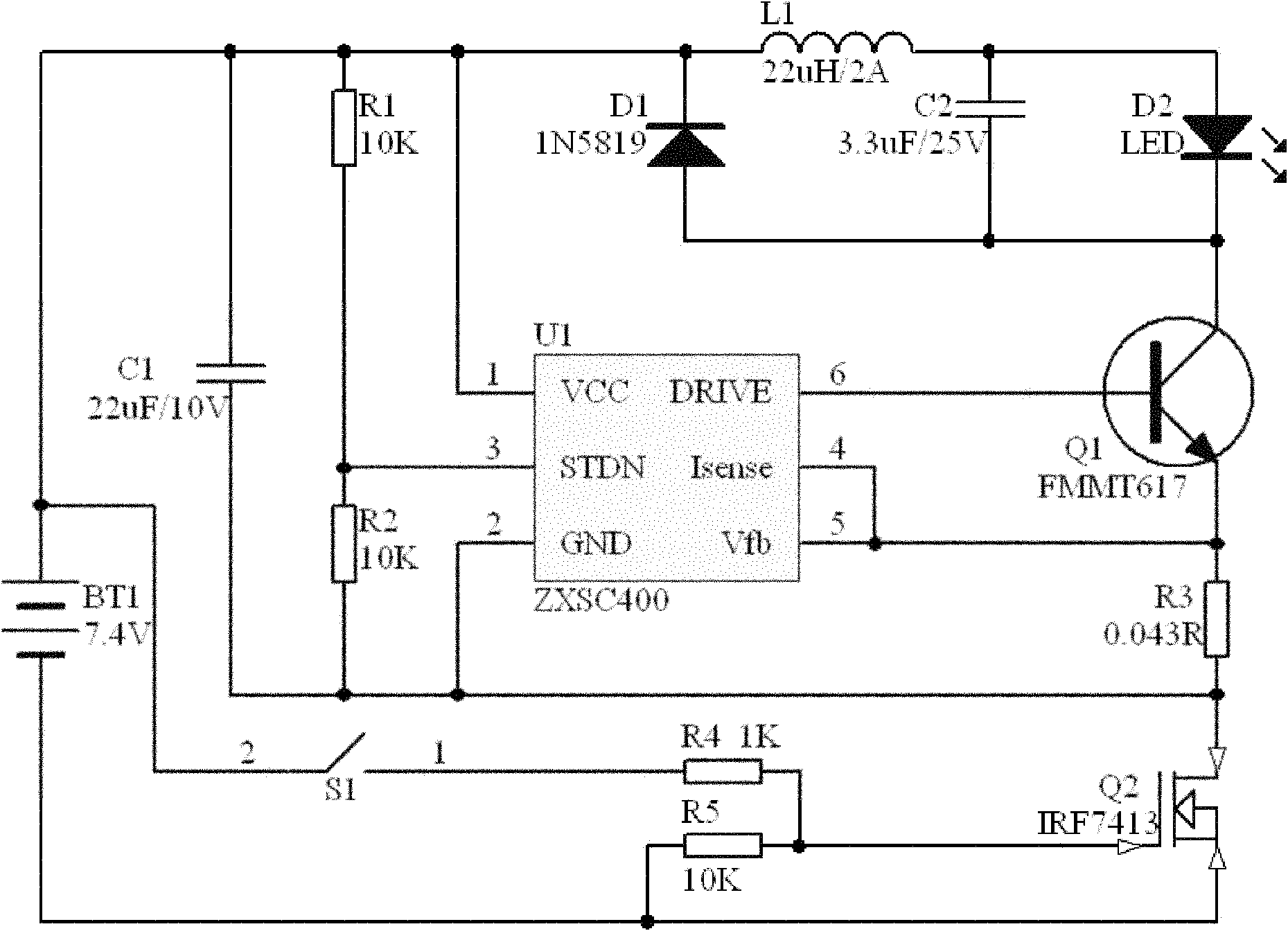
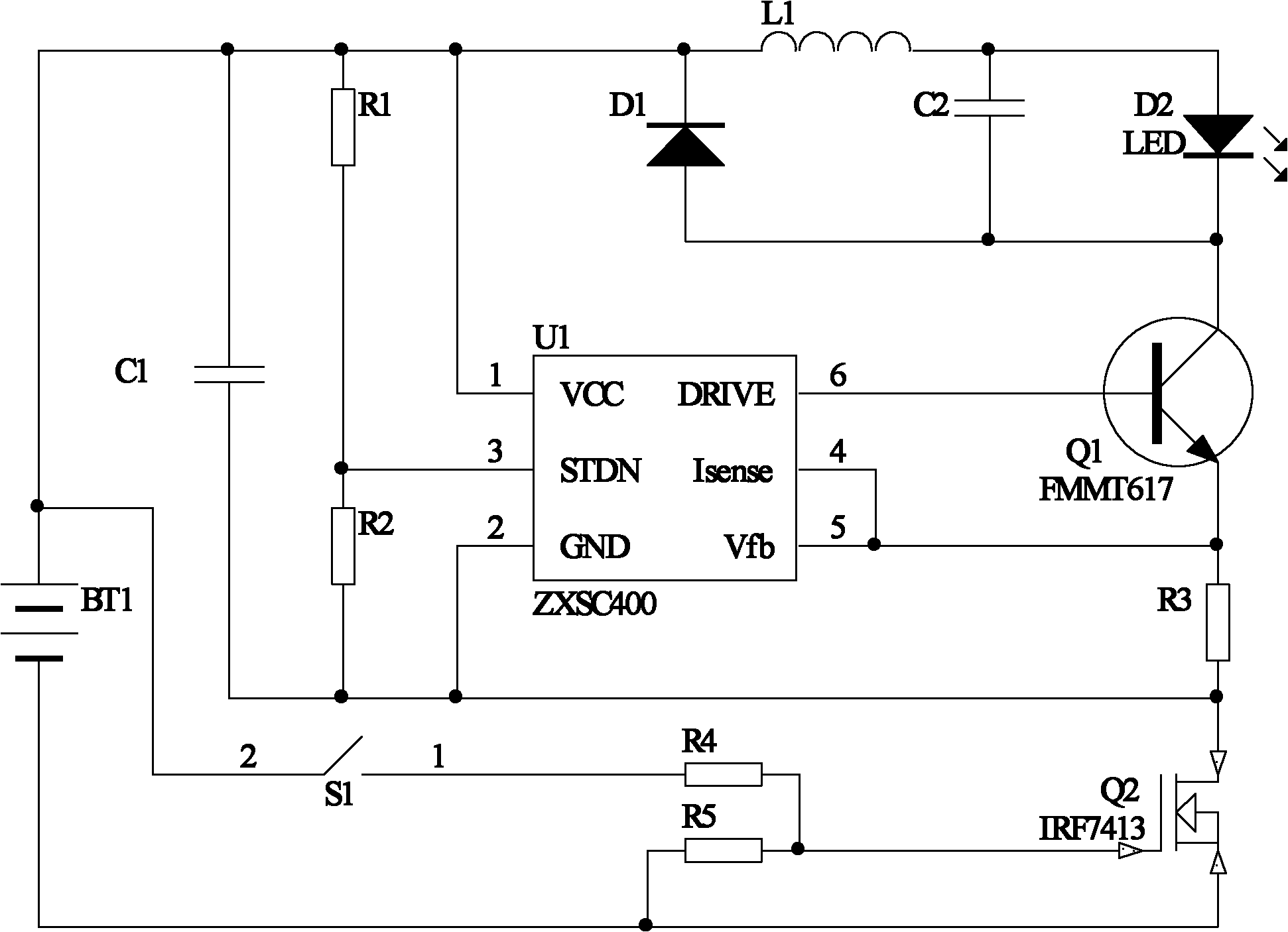
[0021] An embodiment of the present invention is an LED driving circuit, which includes a power supply, an energy storage inductor L1, a triode Q1, a sampling resistor R3, a MOS transistor Q2, a self-locking switch S1, a resistor R1, a resistor R2, a voltage dividing resistor R4, Divider resistor R5 and constant current control chip U1. Alternatively, the drive circuit may also include one or more LEDs.

[0022] Starting from the positive pole of the power supply, connect the positive pole of the power supply, the energy storage inductor L1, the anode of the LED, the cathode of the LED, the collector of the transistor Q1, the emitter of the transistor Q1, the sampling resistor R3, the source of the MOS transistor Q2, the drain of the MOS transistor Q2 and the negative pole of the power supply. For example, R3 is 0.043R, which i...


PUM


Abstract

The invention relates to a light-emitting diode (LED) driving circuit. According to the LED driving circuit, current passes through a power supply positive electrode, an energy storage inductor, an LED anode, an LED cathode, a triode collector, a triode emitter, a sampling resistor, a metal oxide semiconductor (MOS) tube source, an MOS tube drain and a power supply negative electrode sequentially; the power supply positive electrode is connected to an MOS tube grid by a self-locking switch and a voltage division circuit; a pin 1 of a constant-current control chip is a power supply input pin and is connected with the power supply positive electrode; a pin 2 is a ground (GND) pin; a pin 3 is an effective operating enabling pin with a high level, is connected with the power supply positive electrode by a resistor R1 and is connected with the pin 2 by a resistor R2; a pin 4 is a current detection pin; a pin 5 is a voltage detection feedback pin, the pin 4 and the pin 5 are connected and are connected with the triode emitter and the sampling resistor respectively, and the other end of the sampling resistor is connected with the pin 2; and a pin 6 is a pulse-width modulation (PWM) driving pin and is connected with a triode base. The LED driving circuit also comprises a filter capacitor which is connected in parallel with an LED.

Description

【Technical field】 [0001] The invention relates to an LED driving circuit, in particular to an LED constant current driving circuit. 【Background technique】 [0002] With the continuous development of science and technology, new products and new technologies are constantly innovating. As a new type of light source, LED has the characteristics of energy saving, environmental protection and high efficiency. A variety of LED driver circuits. [0003] At present, DC-DC chopping technology is used to drive LED in low-voltage places. It has the advantages of low power consumption, high efficiency, stability and reliability, small size per unit power, light weight, etc., but its cost is high, the circuit is complicated, and easy to use. Damage, strong high-frequency interference and other shortcomings have brought inconvenience to users. [0004] Therefore, the prior art needs to be improved. 【Content of invention】 [0005] In view of this, it is necessary to propose a high-effi...

Claims


Application Information

Patent Timeline
Patent Type & Authority Applications(China)
IPC IPC(8): H05B37/02
Inventor 周明杰孙占民
Owner OCEANS KING LIGHTING SCI&TECH CO LTD
Why Eureka
Eureka Blog
Learn More