Light source device and endoscope system

A technology of a light source device and an endoscope, applied in the field of endoscope systems, can solve problems such as inability to obtain images and difficulty in obtaining bright images

Active Publication Date: 2012-05-23
OLYMPUS CORP
View PDF6 Cites 30 Cited by
  • Summary
  • Abstract
  • Description
  • Claims
  • Application Information

AI Technical Summary

Problems solved by technology

[0008] However, in a field sequential endoscope that irradiates red light, green light, and blue light sequentially in time series, as will be

Method used


Image

  • Light source device and endoscope system
  • Light source device and endoscope system
  • Light source device and endoscope system

Examples


no. 1 approach

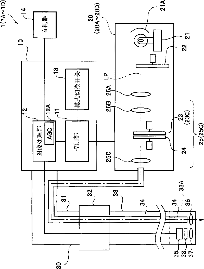
[0042] The endoscope system 1 according to the first embodiment of the present invention is capable of narrow-band light observation as special light observation in addition to ordinary light observation. That is, if figure 1 As shown, the endoscope system 1 includes a light source device 20 , a main body 10 , and an endoscope 30 capable of selectively supplying respective illumination lights for ordinary light observation and narrowband light observation. The endoscope 30 has an operation unit 32 , an elongated insertion unit 33 inserted into the digestive canal or the like of a subject, and a universal cable 31 . An imaging optical unit 37 , a CCD 35 that is a field sequential imaging unit, and an illumination optical unit 36 ​​that emits illumination light are arranged in the front end portion 33A of the insertion unit 33 . The illumination light from the light source device 20 is guided to the illumination optical section 36 through the light guide 34 inserted into the i...

no. 2 approach

[0086] Next, an endoscope system 1B according to a second embodiment will be described. The endoscope system 1B of the present embodiment is similar to the endoscope system 1 of the first embodiment, and therefore the same components are assigned the same reference numerals and their descriptions are omitted.

[0087] The endoscope system 1B of the present embodiment can perform fluorescence observation (AFI), which is special light observation, in addition to ordinary light observation. As already explained, in the case of fluorescence observation, the fluorescence image is combined with the image obtained by using green light which is strongly absorbed by hemoglobin, and displayed as a pseudocolor image in which neoplastic lesions and normal mucous membranes are enhanced in different tones in monitor 14. This is based on the characteristic that when irradiated with blue excitation light, autofluorescence (fluorescence emitted by fluorescent substances such as collagen prese...

no. 3 approach

[0093] Next, an endoscope system 1C and a light source device 20C according to the third embodiment will be described. Since the endoscope system 1C of the present embodiment is similar to the endoscope system 1 and the like of the first embodiment, the same components are assigned the same reference numerals and description thereof will be omitted.

[0094] The endoscope system 1C of the present embodiment is capable of narrow-band light observation (NBI) and fluorescence observation (AFI), which are special light observations, in addition to ordinary light observation (WLI). That is, the endoscope system 1C has both the functions of the endoscope system 1 and the functions of the endoscope system 1B.

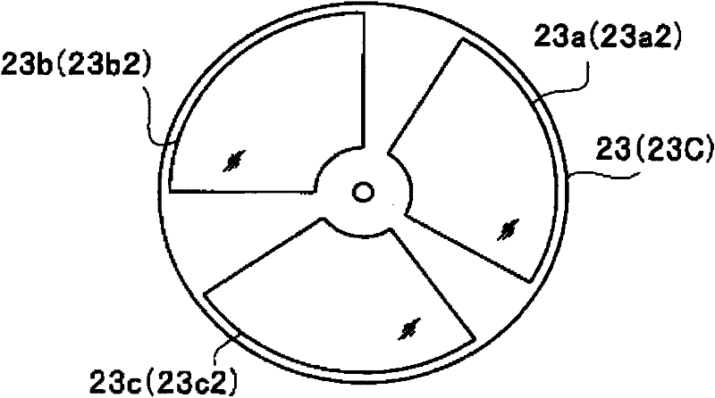
[0095] Such as Figure 9 As shown, the first rotary filter unit 23C of the light source device 20C has three filters including a Mg filter on the inner periphery, and three filters 23a1 and 23b1 including a magenta 2 (Mg2) filter on the outer periphery. , 23c1. Furthermore,...


PUM


Abstract

A light source device (20) comprises a first rotational filter part (23) in which a blue filter (23a), a green filter (23b), and a magenta filter (23c) can be disposed in a light path (LP), a second rotational filter part (24) in which an yellow filter (24a) can be disposed therein, and a band selection filter part (22) in which an NBI filter for limiting blue or green light to a narrow band can be disposed therein. The first and second rotational filter parts (23, 24) can be controlled so that in the case of normal light imaging, the yellow filter (24a) is disposed in the light path (LP) when the magenta filter (23c) is disposed in the light path (LP), and in the case of narrow band imaging, the NBI filter is disposed in the light path (LP), and the yellow filter (24a) is disposed in thelight path (LP) when the green filter (23b) is disposed in the light path (LP).

Description

technical field [0001] The present invention relates to a light source device for providing illumination light to a medical endoscope inserted into a subject to observe tissues in the body and an endoscope system having the above light source device, in particular to a device for providing white light observation and A light source device for illumination light for special light observation, and an endoscope system having the light source device. Background technique [0002] The observation target part of the medical endoscope is the inside of a living body, so a light source device for illuminating the inside of the body is required. The illumination light generated by the light source device illuminates the tissue to be observed from the distal end portion having the imaging portion via a light guide inserted into the insertion portion of the endoscope. [0003] Here, as observation with an endoscope, a common light observation using visible light (White Light Imaging: W...

Claims


Application Information

Patent Timeline
IPC IPC(8): A61B1/06A61B1/00
CPCA61B1/063A61B1/043A61B1/0646A61B1/0638A61B1/00009A61B1/000094A61B1/0655
Inventor 越川丰町田亮
Owner OLYMPUS CORP
Why Eureka
Try Eureka