Impact tool

A technology of impact tools and tools, applied in the field of impact tools, to achieve the effect of fast fastening operations

Inactive Publication Date: 2012-05-23
KOKI HLDG CO LTD
View PDF7 Cites 6 Cited by
  • Summary
  • Abstract
  • Description
  • Claims
  • Application Information

AI Technical Summary

Problems solved by technology

Therefore, excess electric power is supplied to the motor, and ineffective power consumption occurs

Method used


Image

  • Impact tool
  • Impact tool
  • Impact tool

Examples


Embodiment Construction

[0061] Embodiments will be described below with reference to the drawings. In the following descriptions, the up-down, front-back, and left-right directions are the same as figure 1 and 2 Corresponds to the directions shown in .

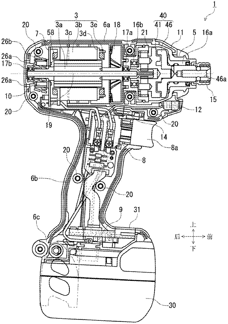
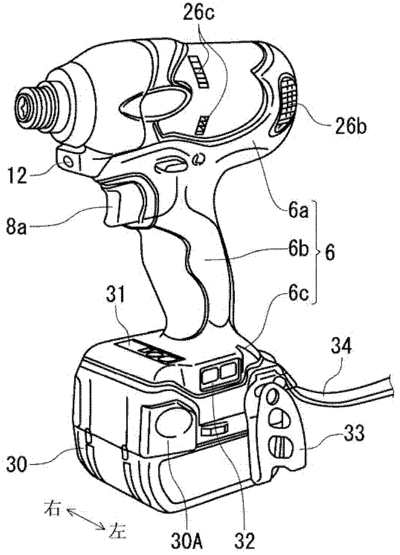
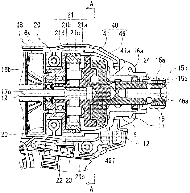
[0062] figure 1 An impact tool 1 according to one embodiment is illustrated. The impact tool 1 drives the impact mechanism 40 with the rechargeable battery pack 30 as a power source and the electric motor 3 as a driving source, and provides rotation and impact to an anvil 46 as an output shaft to transmit continuous torque or intermittent impact force to the tip A tool (not shown), such as a drill bit of an electric screwdriver, to perform operations such as screw tightening or bolt tightening.

[0063] The motor 3 is a brushless DC motor, and is accommodated in a tubular trunk portion 6a of a housing 6 having a substantially T-shape when viewed from the side. The housing 6 is detachable into two substantially symmetrical right and left parts, a...


PUM


Abstract

According to one embodiment, an impact tool includes: a motor (3); and a hammer (11) that is connected to the motor and that has a striking-side surface; and an anvil (16) that is journalled to be rotatable with respect to the hammer (11), that has a struck-side surface and that provides a striking power to a tip tool, wherein the motor (3) is drivable in: a first driving mode in which the motor (3) is continuously driven in a normal rotation; a second driving mode in which the motor (3) is intermittently driven only in the normal rotation; and a third driving mode in which the motor (3) is intermittently driven in the normal rotation and in a reverse rotation.

Description

technical field [0001] An aspect of the present invention relates to an impact tool driven by an electric motor and realizes a new type of impact mechanism. Background technique [0002] In the impact tool, the rotary impact mechanism is driven by a motor as a driving source to provide rotation and impact to the anvil, thereby intermittently transmitting the rotary impact force to the tip tool to perform operations such as screw tightening. Brushless DC motors are widely used as electric motors. A brushless DC motor is, for example, a DC (direct current) motor without brushes (brushes for rectification). Coils (windings) are provided on the stator side, magnets (permanent magnets) are provided on the rotor side, and the rotor rotates when power driven by an inverter circuit is sequentially applied to predetermined coils. The inverter circuit is constructed using FETs (Field Effect Transistors) and high-capacity output transistors such as IGBTs (Insulated Gate Bipolar Trans...

Claims


Application Information

Patent Timeline
Patent Type & Authority Applications(China)
IPC IPC(8): B25B21/02B25B23/147
CPCB25B21/02B25B23/1475B25B21/026
Inventor 谷本英之高野信宏西河智雅岩田和隆益子弘识山口勇人中川淳司大森和博中村瑞穗内田洋树中野沙路磨
Owner KOKI HLDG CO LTD
Why Eureka
Try Eureka