
Film-forming apparatus

A film-forming device and magnetic field technology, applied in ion implantation plating, coating, electrical components, etc., can solve the problems of substrate surface temperature rise, substrate damage, substrate quality degradation, etc.

Active Publication Date: 2014-05-07
ULVAC INC
View PDF6 Cites 0 Cited by
  • Summary
  • Abstract
  • Description
  • Claims
  • Application Information

AI Technical Summary

Problems solved by technology

[0011] However, in the above-mentioned sputtering apparatus, there is a problem that electrons, argon ions, or metal ions (Cu, Al, Ti, Ta, etc.) that have escaped from the magnetic field formed on the target surface by the magnetic field generator reach the substrate, resulting in substrate damage
In addition, there is a problem that the temperature of the surface of the substrate rises due to electrons colliding with the substrate, resulting in a decrease in the quality of the substrate.

Method used


Image

  • Film-forming apparatus
  • Film-forming apparatus
  • Film-forming apparatus

Examples


Embodiment Construction

[0024] Hereinafter, embodiments of the film forming apparatus according to the present invention will be described based on the drawings.

[0025] In addition, in each drawing used in the following description, in order to make each constituent element a size that can be recognized on the drawings, the dimensions and ratios of each constituent element are suitably different from actual ones.

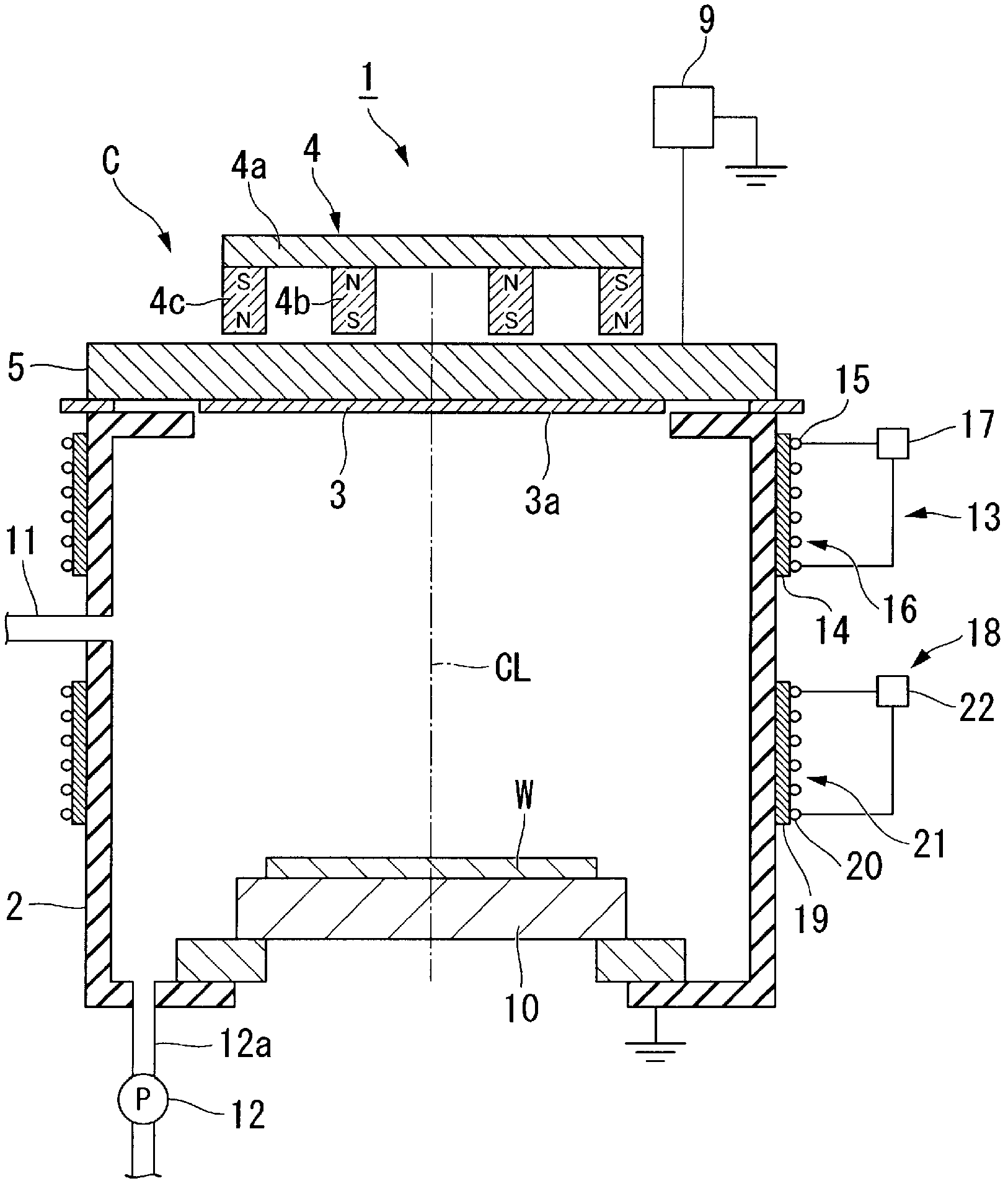
[0026] Such as figure 1 As shown, the film forming apparatus 1 is a DC magnetron sputtering film forming apparatus, and includes a vacuum chamber 2 (chamber) capable of generating a vacuum atmosphere.

[0027] A cathode unit C is attached to the ceiling portion of the vacuum chamber 2 .

[0028] In addition, in the following description, the position close to the top plate part of the vacuum chamber 2 is called "upper", and the position close to the bottom of the vacuum chamber 2 is called "lower".

[0029] The cathode unit C includes a target 3 mounted on a holder 5 . Furthermore, th...


PUM


Abstract

A film formation apparatus includes: a chamber having a side wall and an inner space in which both a body to be processed and a target are disposed a first magnetic field generation section generating a magnetic field in the inner space a second magnetic field generation section disposed at a position close to the target, the second magnetic field generation section generating a magnetic field so as to allow perpendicular magnetic lines of force thereof to pass through a position adjacent to the target; and a third magnetic field generation section disposed at a position close to the body to be processed, the third magnetic field generation section generating a magnetic field so as to induce the magnetic lines of force to the side wall of the chamber.

Description

technical field [0001] The present invention relates to a film forming apparatus for forming a film on the surface of an object to be processed, and particularly to a DC magnetron film forming apparatus using a sputtering method which is one of thin film forming methods. [0002] this application claims priority based on Japanese Patent Application No. 2009-169449 for which it applied on July 17, 2009, and uses the content here. Background technique [0003] Conventionally, for example, a film-forming apparatus (hereinafter referred to as a “sputtering apparatus”) using a sputtering method has been used in a film-forming process in the production process of a semiconductor device. [0004] In sputtering devices for such applications, along with the miniaturization of wiring patterns in recent years, it is strongly required to be able to cover holes or grooves with high aspect ratios and fine patterns on the entire surface of the substrate to be processed with good coverage. ...

Claims


Application Information

Patent Timeline
Patent Type & Authority Patents(China)
IPC IPC(8): C23C14/35H01L21/285H05H1/24
CPCH01L21/2855H01L21/76871C23C14/35H01J37/3452C23C14/351H01J37/3405H01L21/285H05H1/24H01L21/02631
Inventor 小平周司吉浜知之镰田恒吉堀田和正滨口纯一中西茂雄丰田聪
Owner ULVAC INC
Features
  • Generate Ideas
  • Intellectual Property
  • Life Sciences
  • Materials
  • Tech Scout
  • Unparalleled Data Quality
  • Higher Quality Content
  • 60% Fewer Hallucinations
Learn More