Waste gate valve

A technology of wastegate and waste gas passage, which is applied in the direction of lift valve, valve device, engine function, etc., and can solve problems such as complex structure, high price, and insufficient reliability

Inactive Publication Date: 2015-04-01
MITSUBISHI HEAVY IND ENGINE & TURBOCHARGER LTD
View PDF6 Cites 2 Cited by
  • Summary
  • Abstract
  • Description
  • Claims
  • Application Information

AI Technical Summary

Problems solved by technology

As a method for performing this finer control, there is a VG Nozzle, but due to its high price and complicated structure, its reliability at high temperatures for gasoline engines is not sufficient

Method used


Image

  • Waste gate valve
  • Waste gate valve
  • Waste gate valve

Examples


Embodiment Construction

[0051] Hereinafter, preferred embodiments of the present invention will be described in detail by way of example with reference to the accompanying drawings. However, unless otherwise specified, dimensions, materials, shapes, relative arrangements, and the like of components described in the embodiments do not limit the scope of the present invention thereto, and are merely illustrative examples.

[0052] 【Example】

[0053] In the embodiment, the structure of the exhaust gas supply device of the engine to which the wastegate valve of the present invention is applied is the same as Figure 9 shown in the previous structure the same, so the Figure 9 It applies to this embodiment and its description is omitted.

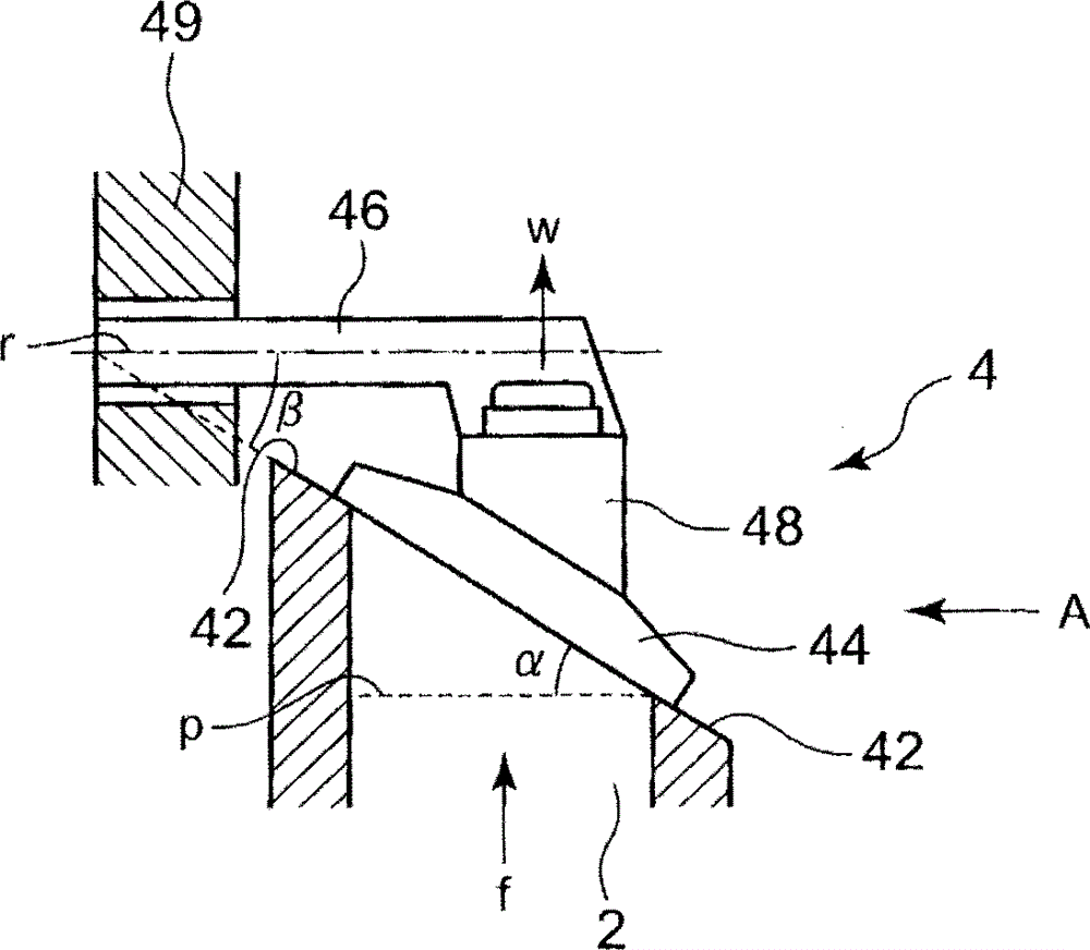
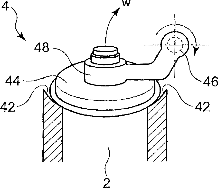
[0054] figure 1 It is a side view showing the wastegate valve of the present invention, and is a partially cross-sectional view. figure 2 yes figure 1 View from direction A.

[0055] use figure 1 and figure 2 The wastegate valve of this embodiment will be des...


PUM


Abstract

In a wastegate valve which is provided in the bypass path bypassing the turbine of the turbocharger in the exhaust gas path and which opens and closes the bypass path, the wastegate valve is provided with a valve seat which is formed in a plane perpendicular to or tilted with an inclination angle with respect to an axial direction of the bypass path, and a valving element which is pivotable around a pivot point which has a relationship of 0°<²<90° with respect to the plane including the valve seat where ² is an inclination angle, the valving element being moved away from or closer to the valve seat by pivotation of the valving element to open or close the valve.

Description

technical field [0001] The present invention relates to a wastegate valve provided in a bypass passage bypassing a turbine of a turbocharger in an exhaust gas passage of an engine to open and close the bypass passage. Background technique [0002] In a turbocharger that uses the energy of exhaust gas from the engine to pressurize the gas supplied to the engine, a bypass passage is provided to prevent over-rotation of the turbocharger due to an increase in exhaust gas pressure. It is connected from the exhaust gas inlet side of the turbine of the turbocharger to the outlet side, and is opened and closed by a wastegate valve. [0003] Figure 9 It is a block diagram of an engine supply and exhaust system to which a wastegate valve is applied. [0004] exist Figure 9 In the engine 52 , an air supply passage 58 is connected via an air supply manifold 56 , and an exhaust passage 60 is connected via an exhaust manifold 54 . [0005] A compressor 70 a of a turbocharger 70 is pro...

Claims


Application Information

Patent Timeline
Patent Type & Authority Patents(China)
IPC IPC(8): F02B37/18F02B37/16F02B39/00
CPCF02B37/183F05D2260/606F16K1/2007F01D17/105F05D2250/313F05D2220/40F02B37/186Y02T10/144F05D2250/314Y02T10/12F02B37/16F02B37/18F02B39/00
Inventor 星彻富田勋横山隆雄林慎之
Owner MITSUBISHI HEAVY IND ENGINE & TURBOCHARGER LTD
Why Eureka
Try Eureka