Centrifugal compressor

A centrifugal compressor and gas compression technology, which is applied in mechanical equipment, engine manufacturing, machine/engine, etc., can solve problems such as leakage and compression efficiency reduction, and achieve the effect of reducing costs and maintaining high compression efficiency

Inactive Publication Date: 2012-05-23
MITSUBISHI HEAVY IND LTD
View PDF12 Cites 7 Cited by
  • Summary
  • Abstract
  • Description
  • Claims
  • Application Information

AI Technical Summary

Problems solved by technology

As a result, the gap T is enlarged, and the gas to be compressed leaks from the gap T, so there is a problem that the compression efficiency is lowered.

Method used


Image

  • Centrifugal compressor
  • Centrifugal compressor
  • Centrifugal compressor

Examples


no. 1 approach

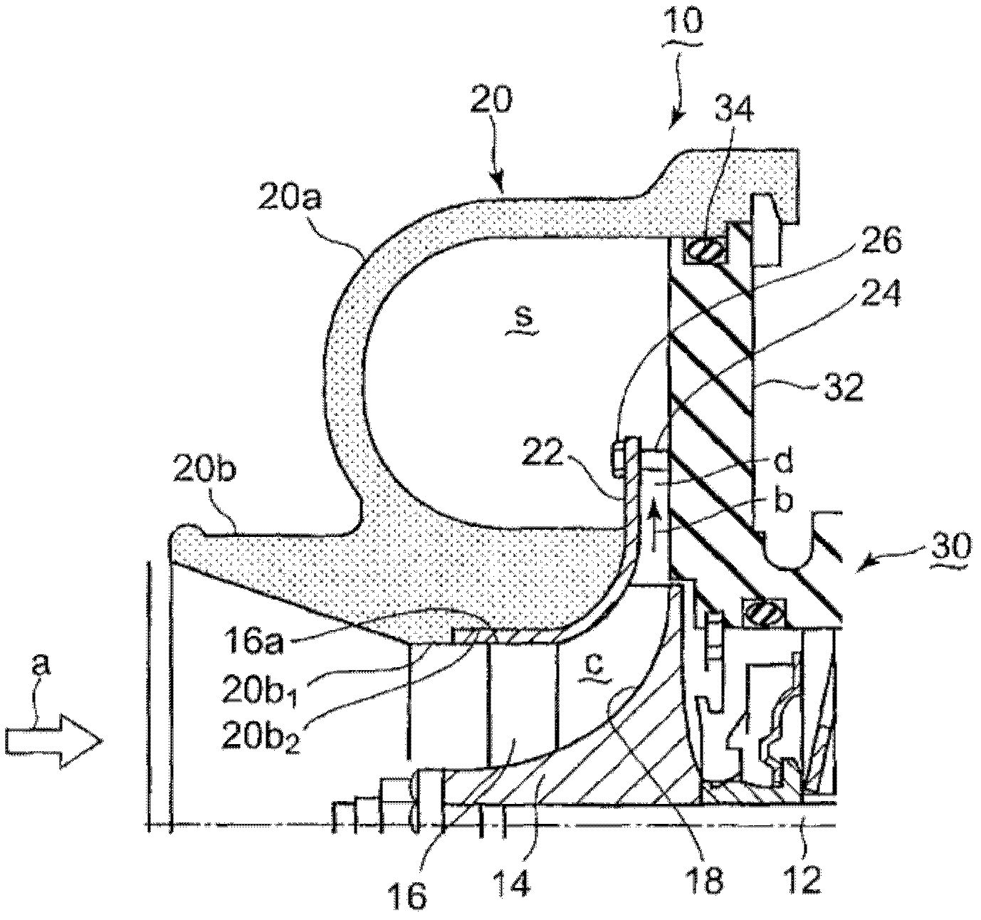
[0052] use figure 1 A first embodiment of the turbocharger of the present invention will be described. figure 1 A part of the compressor unit of the turbocharger 10 according to the present embodiment is shown. Such as figure 1 As shown, a rotating shaft 12 is disposed at the center of a resin housing 20, an impeller 14 is fixedly installed on the outer peripheral surface of the rotating shaft 12, and a plurality of blades 16 are radially arranged on the impeller 14 along the radial direction of the rotating shaft 12. . The hub surface 18 of the impeller 14 is curved from the axial direction of the rotating shaft 12 to the radial direction from the inlet side to the outlet side in the flow direction of the compressed gas (arrow a direction). The resin case 20 is composed of a spiral portion 20 a forming a spiral portion s inside and a flow path forming portion 20 b forming a flow path c of compressed gas.

[0053] The outer end of the blade 16 is formed with a curved pr...

no. 2 approach

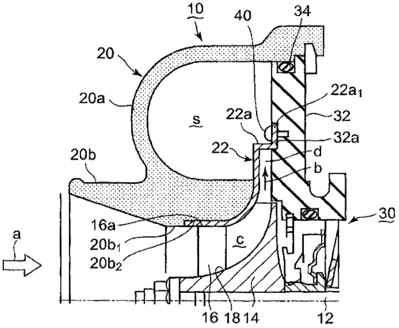
[0060] Next, use figure 2 A second embodiment of the turbocharger of the present invention will be described. Such as figure 2 As shown, in this embodiment, the downstream side end portion 22 a of the annular shroud 22 is formed with two bent portions, and extends until it contacts the partition wall 32 of the bearing housing 30 . A flange portion 22a is formed at the extended end portion 1 . On the other hand, the partition wall 32 is engraved with a flange portion 22a for fitting. 1 The concave portion 32a. Flange part 22a 1 It is connected to the recessed part 32a by the bolt 40.

[0061] In addition, since the flange portion 22a 1 Since it is partially formed in the circumferential direction of the impeller 14, the downstream end portion 22a of the shroud 22 does not block the diffuser d, and does not hinder the flow of the compressed gas in the diffuser d. Other structures are the same as those of the above-mentioned first embodiment. The same reference numeral...

no. 3 approach

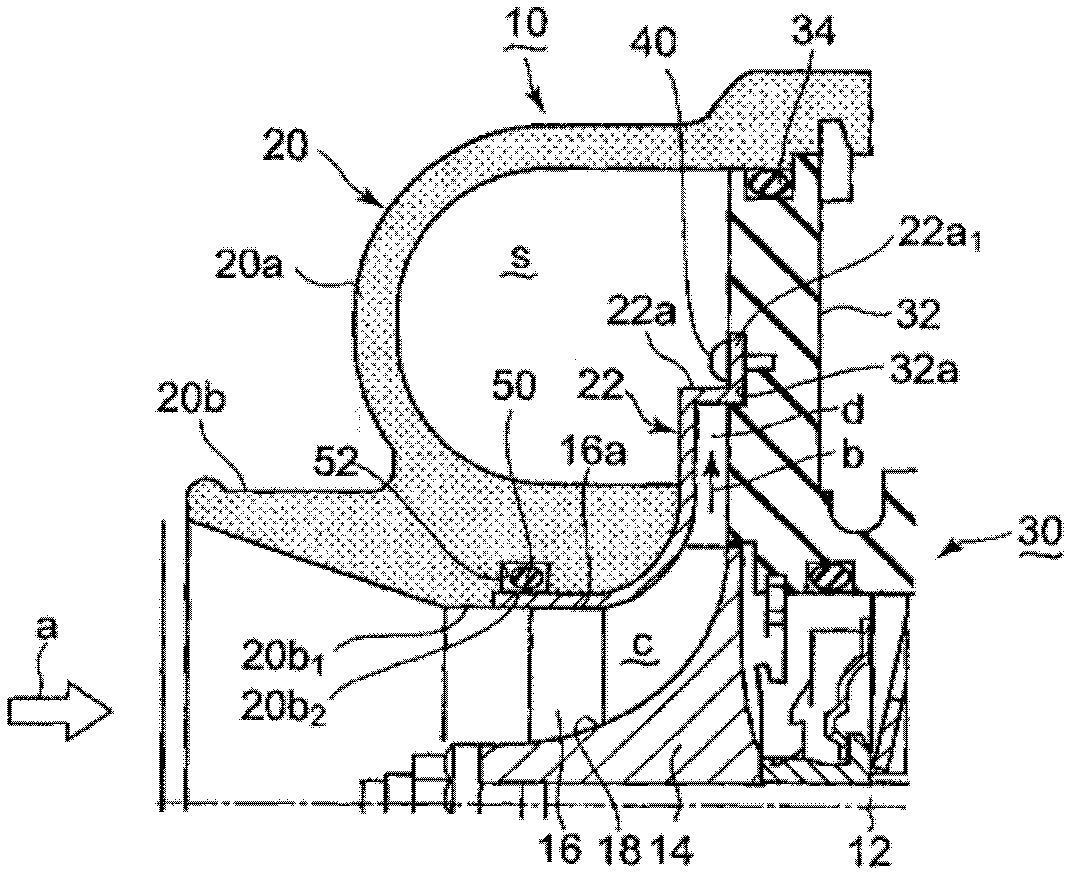
[0064] Next, use image 3 A third embodiment of the turbocharger of the present invention will be described. Such as image 3 As shown, in the present embodiment, in the inlet region of the flow path c, the inner wall 20b of the flow path forming portion 20b engraved on the resin case 20 1 The recess 20b 2 , engraved housing groove 52, in the housing groove 52 housing rubber or resin sealing ring 50. The other structures are the same as those of the above-mentioned second embodiment.

[0065] According to this embodiment, even if the resin case 20 is thermally deformed, the recess 20b 2 When there is a gap between the back surface of the annular shutter 2 (made of metal such as aluminum or carbon steel or ceramics), the compressed gas does not enter the recess 20b because the seal ring 50 is provided. 2 and the annular shroud 22, therefore, the compression efficiency of the compressor will not decrease.

[0066] At the inlet of the impeller 14, the temperature of the com...


PUM


Abstract

It is intended to provide a centrifugal compressor equipped with a resin housing which does not compression efficiency without offsetting merits such as weight saving and cost reduction. A centrifugal compressor 10 includes a resin housing 20 formed by a volute section 20a and a path forming section 20b. An impeller 14 fixed to a rotating shaft 12 in a center of the path forming section 20b. An annular shroud 22 is arranged in a depression 20b 2 carved in an inner wall 20b 1 of the path forming section 20b. The annular shroud 22 forms an outer wall of a flow path c for a gas to be compressed and an outer wall of a diffuser d (static-pressure increasing region). A downstream end of the annular shroud 22 is fixed via a spacer 24 to a wall 32 by a bolt 6. The wall 32 constitutes a part of a bearing housing 30. Even when the resin housing 20 thermally deforms, a clearance T between the annular shroud 22 and a curved profile 16a of the blade 16 can be kept at a set dimension.

Description

technical field [0001] The present invention relates to a centrifugal compressor having a resin casing used for, for example, a turbocharger or the like. Background technique [0002] A turbocharger (exhaust turbocharger) mounted on a motor vehicle, etc. uses an exhaust turbine to drive a compressor and supply intake air compressed by the compressor to the engine, and the exhaust turbine is driven by the energy of the exhaust gas . In such a turbocharger, a bearing housing for rotatably supporting a rotary shaft is provided between a turbine housing of the exhaust turbine and a housing of the turbo compressor. The impeller of the turbocompressor and the wheel of the exhaust turbine are fixedly installed on the rotating shaft passing through the bearing housing. [0003] A bearing mechanism that rotatably supports the rotating shaft is accommodated in the bearing housing. A sealing wall is provided at the boundary between the bearing housing and the compressor housing, and...

Claims


Application Information

Patent Timeline
Patent Type & Authority Applications(China)
IPC IPC(8): F04D29/44F04D17/10
CPCF04D29/4206F04D29/023F04D29/441F05D2300/43F05D2250/52F04D29/162F04D29/4213F04D29/685F05D2220/40F05D2300/502Y10S415/00
Inventor 茨木诚一富田勋阵内靖明御子神隆东条正希北田明夫
Owner MITSUBISHI HEAVY IND LTD
Why Eureka
Try Eureka