
Multi-beam laser power control circuit and image forming apparatus using the same

A technology of power control and automatic power control, which is applied to lasers, equipment for electrical recording technology using charge patterns, laser components, etc., to achieve the effect of reducing the time period

Inactive Publication Date: 2014-08-06
RICOH KK
View PDF8 Cites 0 Cited by
  • Summary
  • Abstract
  • Description
  • Claims
  • Application Information

AI Technical Summary

Problems solved by technology

However, the number of photodiodes can be lower than the number of semiconductor lasers; sometimes, only one photodiode is integrated

Method used


Image

  • Multi-beam laser power control circuit and image forming apparatus using the same
  • Multi-beam laser power control circuit and image forming apparatus using the same
  • Multi-beam laser power control circuit and image forming apparatus using the same

Examples


no. 1 example

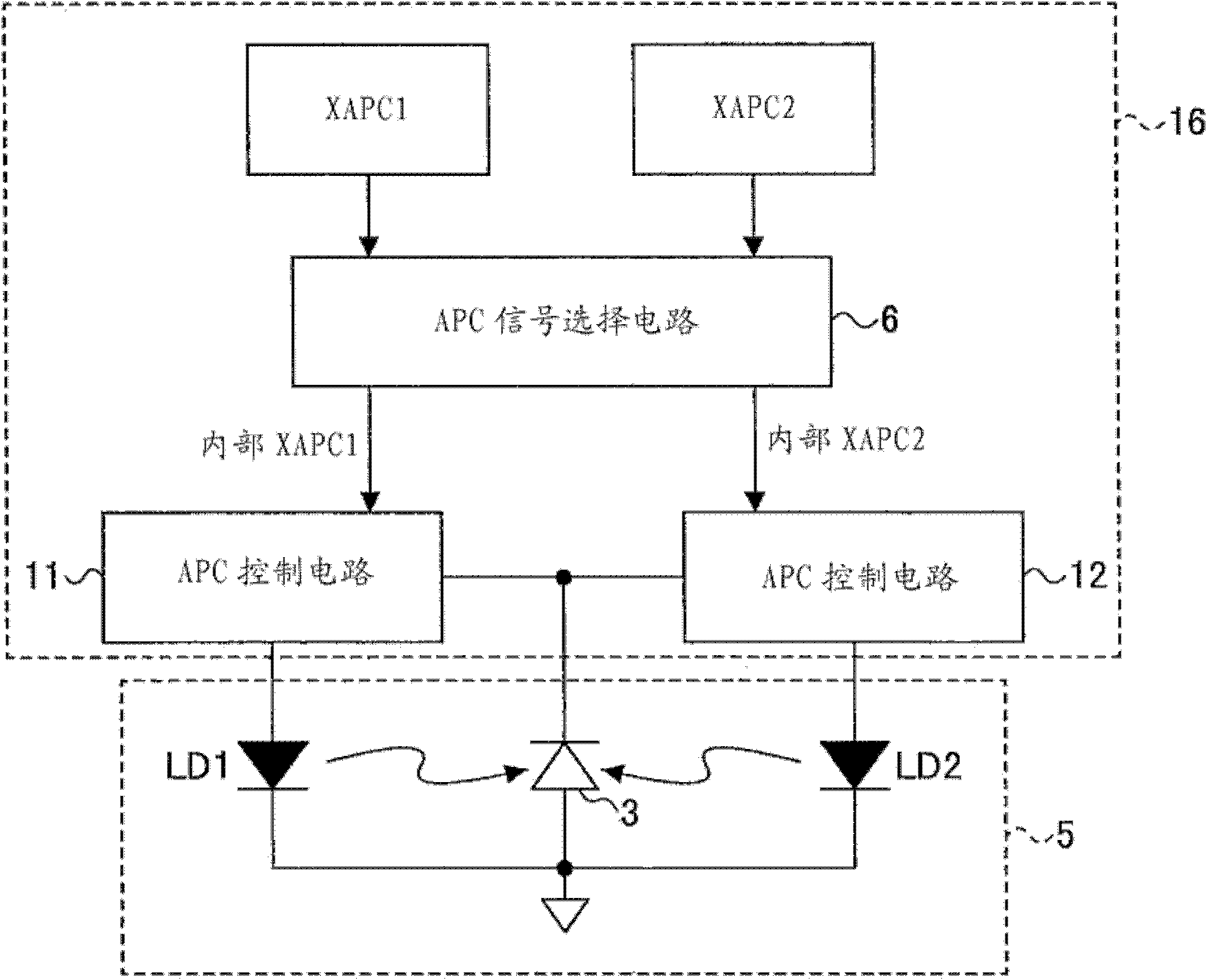
[0044] figure 1 is a schematic block diagram of the multi-beam laser power control circuit 16 according to the first embodiment of the present invention. exist figure 1 In , in addition to the block diagram of the multi-beam laser power control circuit 16, a block diagram of the semiconductor laser array (multi-beam unit) 5 is also included.

[0045] Such as figure 1 As shown, the semiconductor laser array (multi-beam unit) 5 includes two semiconductor lasers ( LD1 , LD2 ) and one photodiode 3 corresponding to the two semiconductor lasers ( LD1 , LD2 ). in addition, figure 1 The multi-beam laser power control circuit 16 includes an APC signal selection circuit 6, an APC control circuit 11 for LD1, an APC control circuit 12 for LD2, and an APC execution signal input terminal for externally inputting an APC execution signal. The APC execution signal is input to each APC execution signal input terminal, and the number of APC execution signals corresponds to the number of ...


PUM


Abstract

Disclosed is a multi-beam laser power control circuit, comprising: a light receiving element receiving power output from a semiconductor laser to control the output power of a semiconductor laser array with a plurality of semiconductor lasers; an automatic power control circuit (APC circuit), based on receiving a corresponding automatic power control execution signal to control the emission power output from the semiconductor laser so as to be set to a predetermined emission power based on the output of the light receiving element; and an APC execution signal input terminal to input the corresponding automatic power control an execution signal in which, when a plurality of APC execution signals input to corresponding APC execution signal input terminals overlap, an automatic power control circuit (APC circuit) to be operated preferentially is determined based on the input timing of the APC execution signal, and is operated .

Description

technical field [0001] The present invention relates to a multi-beam laser power control circuit used in an image forming apparatus, and more particularly, to a multi-beam laser power control circuit that detects the output power of a plurality of semiconductor lasers using photodiodes and controls the output power as desired. Background technique [0002] In printers, optical disks, optical communications, etc., semiconductor lasers are widely used due to their compact size, low cost, and ease of obtaining laser light by simply passing an electric current. However, the current-output power (light amount) characteristics of semiconductor lasers vary depending on the ambient temperature. Due to this feature, special output power control needs to be performed in order to obtain a fixed (constant) optical output power. The power (optical output power) control is called automatic power control (Automatic Power Control, APC). [0003] In automatic power control (APC), before th...

Claims


Application Information

Patent Timeline
Patent Type & Authority Patents(China)
IPC IPC(8): H01S5/0683H01S5/062
CPCH01S5/0427H01S5/4025H04N9/3129H01S5/06832G03G15/00H01S5/0683
Inventor 釜谷智彦
Owner RICOH KK
Learn More