
Diversity receiver and transceiver

A receiver and transceiver technology, applied in the field of short-range device applications, can solve problems such as limiting the available area of ​​the antenna

Inactive Publication Date: 2012-05-23
NXP USA INC
View PDF4 Cites 9 Cited by
  • Summary
  • Abstract
  • Description
  • Claims
  • Application Information

AI Technical Summary

Problems solved by technology

Short-range devices are often small, which limits the area available for several antennas, or limits the power available for receiver-side digital processing units and connected analog-to-digital converters for diversity receiver signal processing

Method used


Image

  • Diversity receiver and transceiver
  • Diversity receiver and transceiver
  • Diversity receiver and transceiver

Examples


Embodiment Construction

[0025] refer to Figure 4 , showing a first schematic example of a diversity antenna system. The illustrated diversity antenna system 70 includes a diversity transmitter 72 having a plurality of transmitter side antennas 74 , 76 . The diversity transmitter may be arranged to generate a signal comprising at least one sequence of data packets having the same payload and a different identifier for each of said data packets. Each of the identifiers may identify a corresponding one of the plurality of transmitter-side antennas 74,76. And the diversity transmitter 72 may be arranged to transmit at least two of said signals sequentially at different points in time on said plurality of transmitter side antennas 74,76. Also the illustrated diversity antenna system 70 may include a receiver 78 including a first receiver side antenna 80 . The receiver 78 may be arranged to sequentially receive at least one sequence of signals on the first receiver side antenna 80, and when the error c...


PUM


Abstract

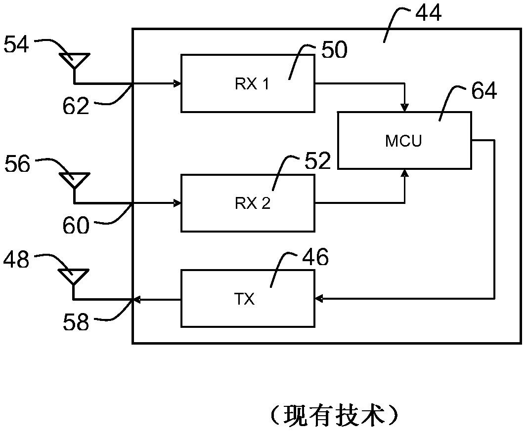
A diversity receiver (112) comprises a plurality of receiving paths connected to a receiver circuit (174). Each of the receiving paths comprises an antenna (114, 1 16) receiving a signal, connected to a matching network (170, 176) connected to a receive amplifier (172, 178). The receiver circuit is connected to a signal level comparison circuit for providing a relative comparison value indicating one of the receiving paths receiving the signal with a relative maximum strength. The signal level comparison circuit comprises a comparator circuit (182) connected to the receiver circuit receiving a currently received signal level, and to a logic control unit (180) being arranged to select one of the receive paths to provide the currently received signal to the receiver circuit.

Description

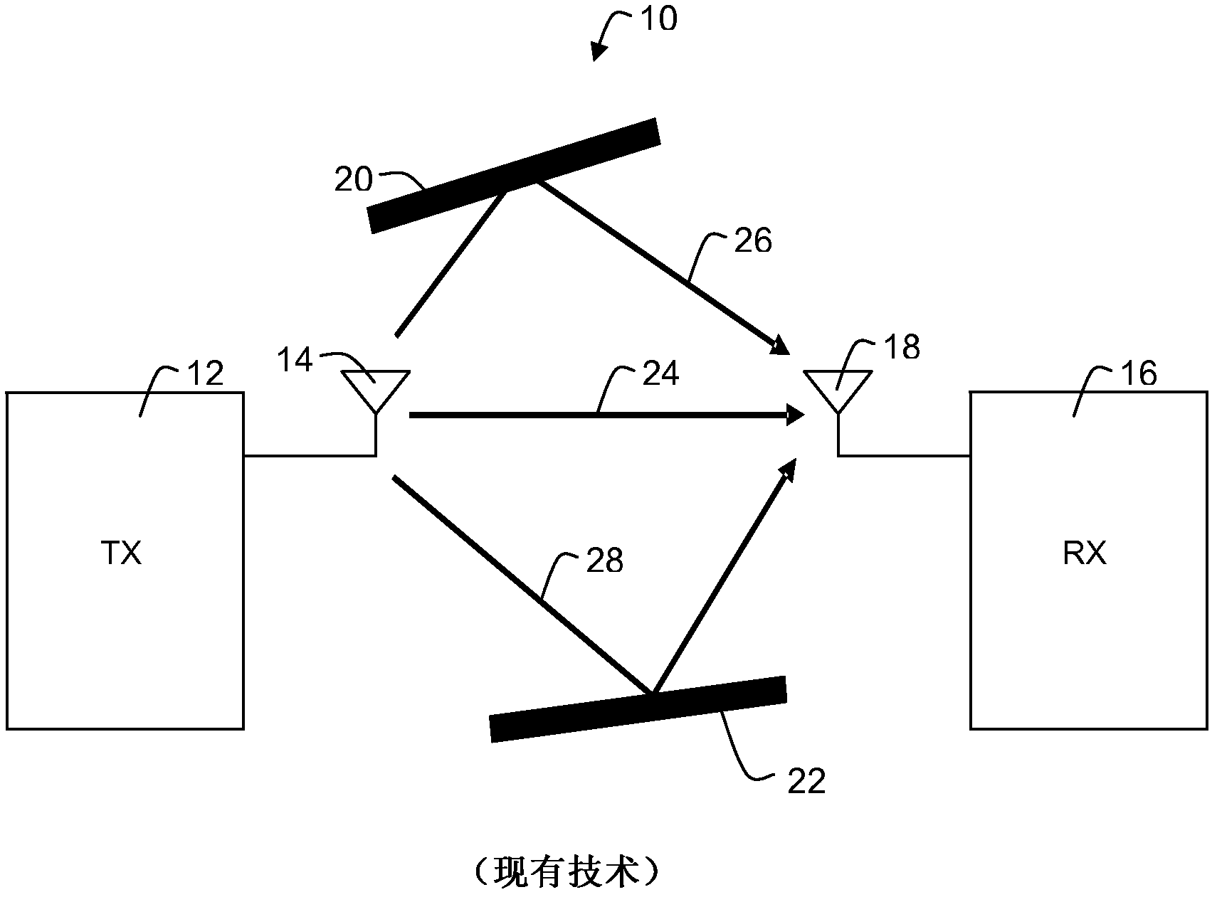
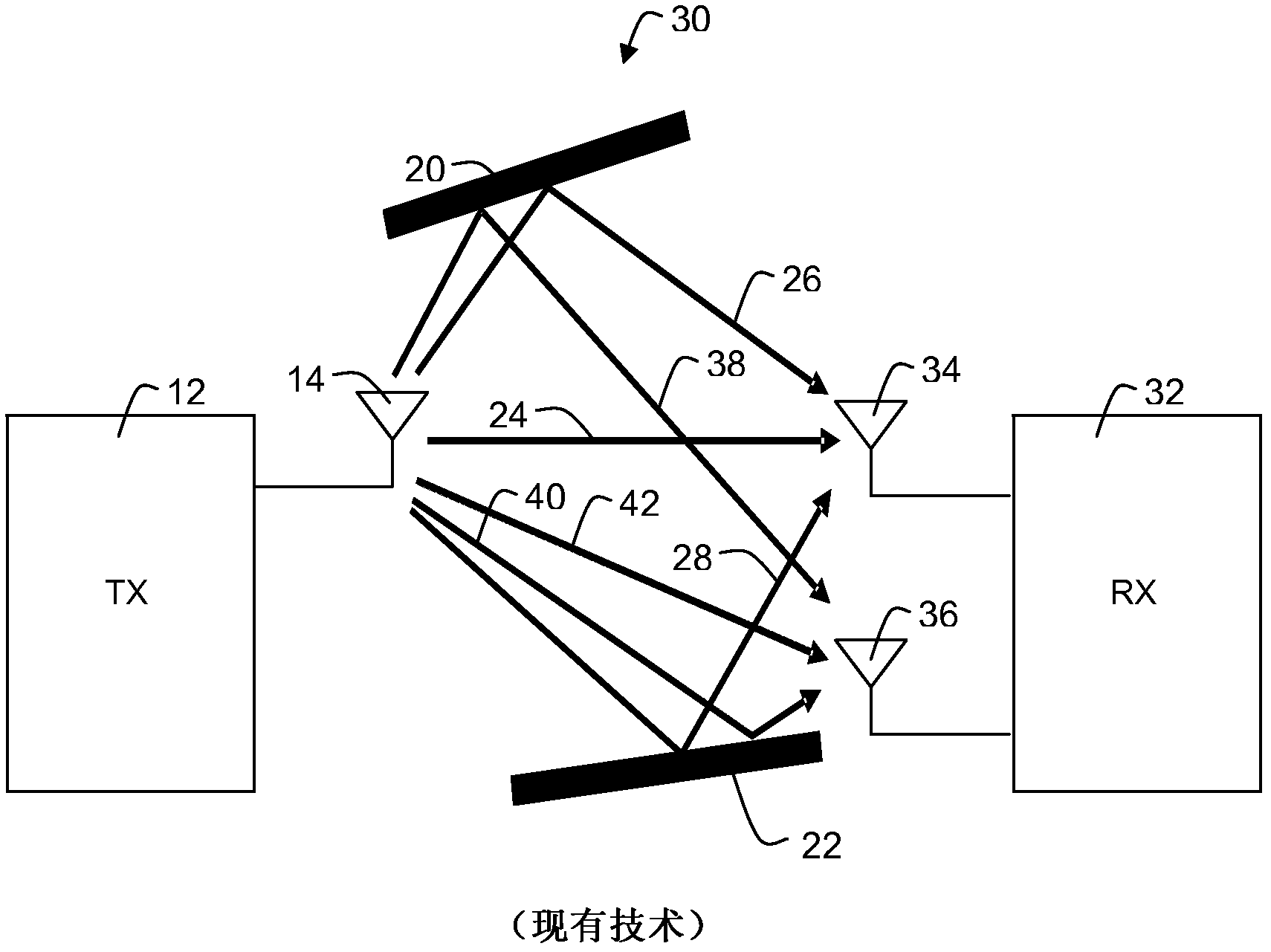
technical field [0001] The present invention relates generally to radio frequency communication systems, and more particularly, to a diversity receiver, diversity transceiver, and short-range device (SRD) application utilizing antenna diversity techniques. Background technique [0002] Antenna diversity is a method of coping with multipath fading of received signals in wireless communication systems, as encountered in radio frequency (RF) communications within or between buildings, where multipath transmissions can lead to destructive interference and thus Reduced range for reliable communication. [0003] For example, if figure 1 As shown in , a communication system 10 without antenna diversity may include a transmitter (TX) or transmitter 12 with a single transmitter-side antenna 14 and a receiver (RX) 16 with a receiver-side antenna 18 . A signal may be a change in a physical quantity that carries information, such as an electromagnetic wave. The signal may eg be a rad...

Claims


Application Information

Patent Timeline
Patent Type & Authority Applications(China)
IPC IPC(8): H04B7/08
CPCH04B7/0811
Inventor 劳伦特·戈捷
Owner NXP USA INC
Learn More