

Optical lens group
An optical lens and lens technology, which is applied in the field of optical lens groups, can solve the problems of high sensitivity and long total length of the second positive lens that cannot be improved
- Summary
- Abstract
- Description
- Claims
- Application Information
AI Technical Summary
Problems solved by technology
Method used
Image

Examples
no. 1 example 》
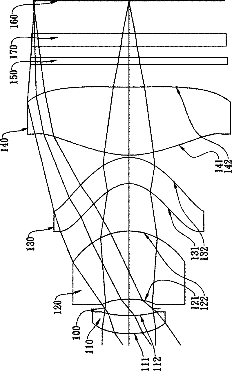
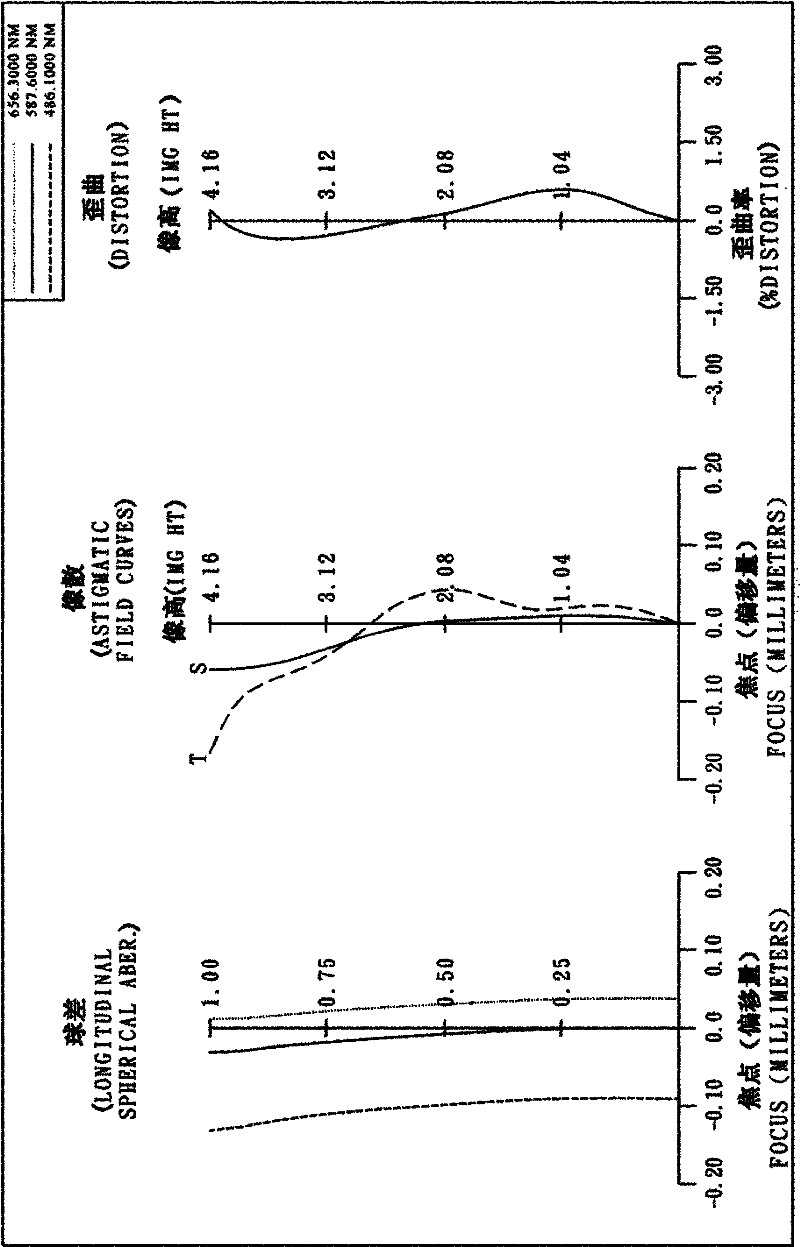
[0116] Please refer to the first embodiment of the present invention Figure 1A , please refer to the aberration curve of the first embodiment Figure 1B . The optical lens group of the first embodiment is mainly composed of four lenses, which include sequentially from the object side to the image side:
[0117] A first lens 110 with positive refractive power, its object-side surface 111 is convex and image-side surface 112 is concave, its material is plastic, the object-side surface 111 and image-side surface 112 of the first lens 110 are both aspherical ;
[0118] A second lens 120 with positive refractive power, the object side surface 121 is concave and the image side surface is convex 122, its material is plastic, the object side surface 121 and image side surface 122 of the second lens 120 are both aspherical ;
[0119] A third lens 130 with negative refractive power, its object-side surface 131 is concave and image-side surface 132 is convex, its material is plastic,...
no. 2 example 》
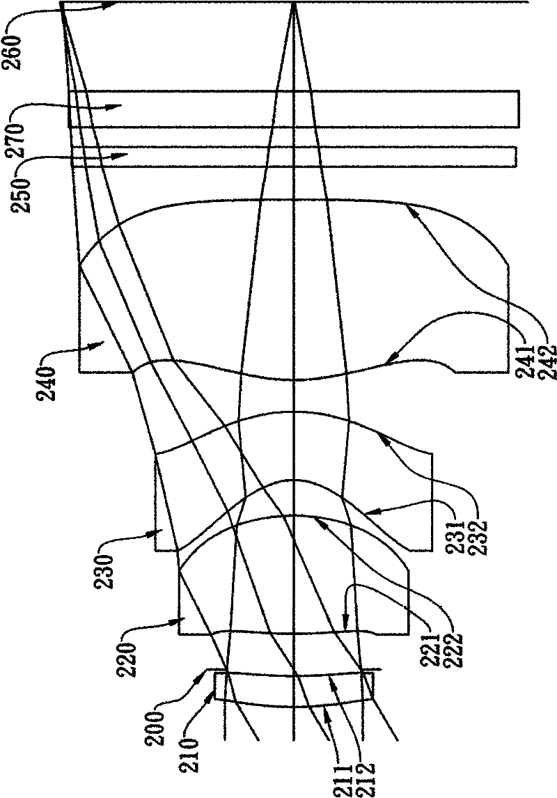
[0145] Please refer to the second embodiment of the present invention Figure 2A , for the aberration curve of the second embodiment, please refer to Figure 2B . The optical lens group of the second embodiment is mainly composed of four lenses, which include sequentially from the object side to the image side:
[0146] A first lens 210 with positive refractive power, its object side surface 211 is convex and image side surface 212 is concave, its material is plastic, the object side surface 211 and image side surface 212 of the first lens 210 are both aspherical ;
[0147] A second lens 220 with positive refractive power, its object-side surface 221 and image-side surface are convex 222, its material is plastic, the object-side surface 221 and image-side surface 222 of the second lens 220 are both aspherical ;
[0148] A third lens 230 with negative refractive power, its object side surface 231 is concave and image side surface 232 is convex, its material is plastic, the ob...
no. 3 example 》
[0168] Please refer to the third embodiment of the present invention Figure 3A , for the aberration curve of the third embodiment, please refer to Figure 3B . The optical lens group of the third embodiment is mainly composed of four lenses, which include sequentially from the object side to the image side:
[0169] A first lens 310 with positive refractive power, its object side surface 311 is concave and image side surface 312 is convex, its material is plastic, the object side surface 311 and image side surface 312 of the first lens 310 are both aspherical ;
[0170] A second lens 320 with positive refractive power, its object side surface 321 is concave and image side surface 322 is convex, its material is plastic, the object side surface 321 and image side surface 322 of the second lens 320 are both aspherical ;
[0171] A third lens 230 with negative refractive power, its object side surface 331 is concave and image side surface 332 is convex, its material is plasti...
PUM
 Abstract
Description
Claims
Application Information