Deformed cylindrical section straightening device

A barrel section and arc-shaped technology, which is applied in the field of correction devices, can solve the problems that the roundness and the concentricity requirements of the two barrel sections cannot be guaranteed, the oil circuit of the annular fixed ring is complicated, and the barrel section rotation cannot be realized, so as to improve the assembly Alignment and welding quality, avoiding driving safety accidents and economic losses, and improving the efficiency of correcting work

Inactive Publication Date: 2012-06-06
XI AN RAILWAY TRANSPORTATION EQUIP
View PDF6 Cites 11 Cited by
  • Summary
  • Abstract
  • Description
  • Claims
  • Application Information

AI Technical Summary

Problems solved by technology

[0007] The whole set of internal clamping device includes a fixed oil cylinder ring and several telescopic wires and sleeves. The structure is complex, and the roundness is adjusted mechanically. It is necessary to manually adjust the screw stroke point by point for different deformation points. For large-diameter tank operations The safety and reliability are poor, and at the same time relying on manual observation of the diameter, the requirements for roundness and concentricity of the two cylinder sections cannot be guaranteed
If the hydraulic method is used, the oil circuit of the entire annular fixed ring is complicated and the number of oil pipes is too large
For this kind of device, the whole set of support ring must be set on the cylinder section before the deformation of the cylinder section, so the diameter of the support ring must be much larger than that of the workpiece, which will inevitably result in a huge structure, and the operation site must also be equipped with lifting equipment
Whether it is manual or hydraulic, this method cannot realize the rotation of the barrel joint, and cannot meet the welding requirements.

Method used


Image

  • Deformed cylindrical section straightening device
  • Deformed cylindrical section straightening device
  • Deformed cylindrical section straightening device

Examples


Embodiment 1

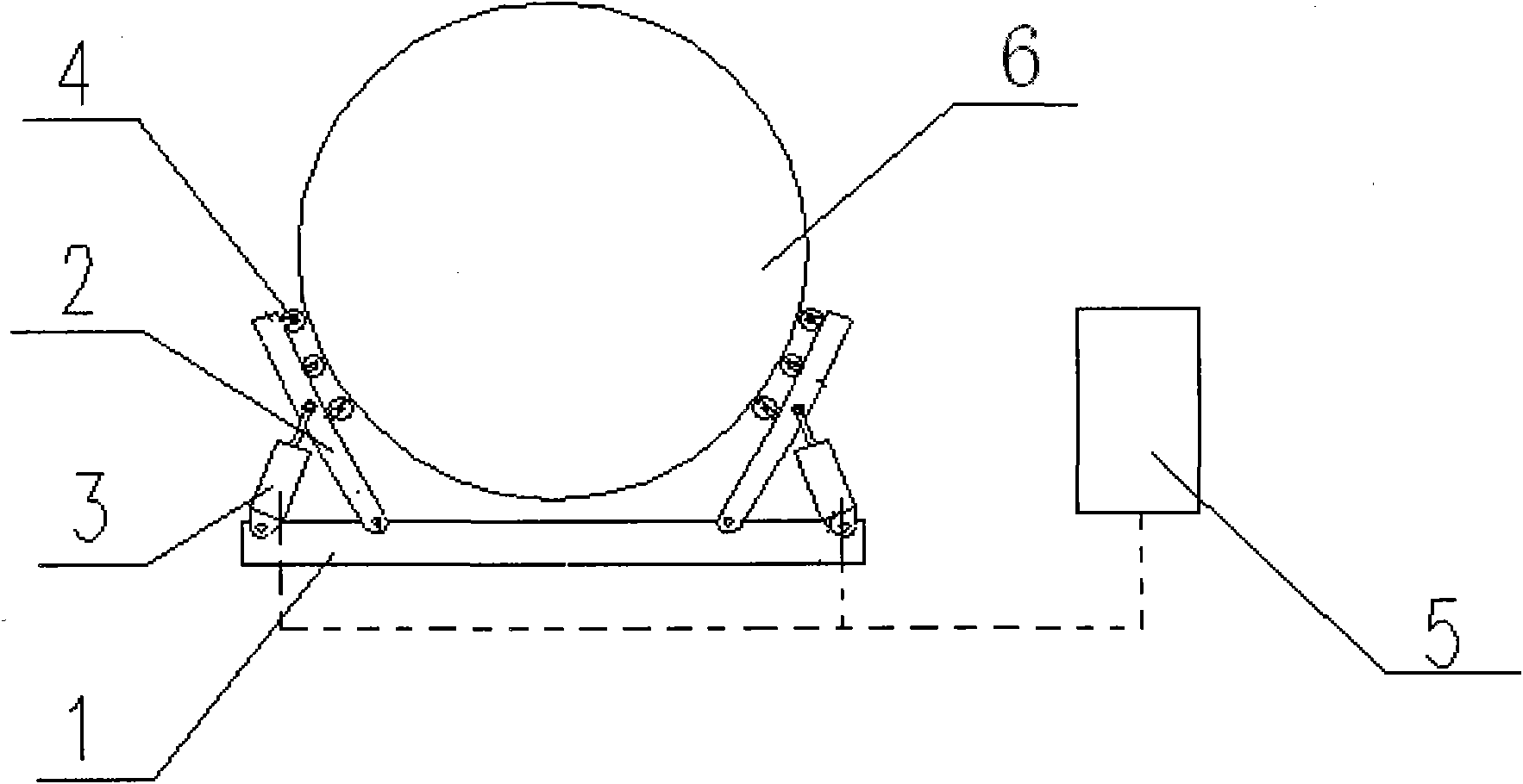
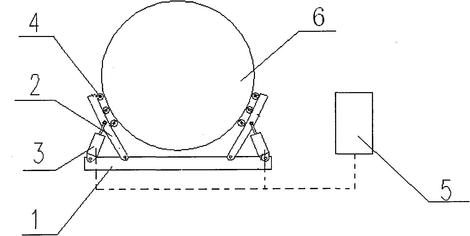
[0026] figure 2 It is a schematic diagram of the use state of the tube section deformation correction device provided in the first embodiment of the present invention. The tube section deformation correction device provided in this embodiment includes a frame 1, a lead frame 2, a hydraulic cylinder 3, and an electrical connection with the hydraulic cylinder 3. control system 5.

[0027] As shown in the specific embodiment shown in the figure, in the tube section deformation correction device, two guide frames 2 are hinged on the frame 1 to form mirror symmetry. The rectified cylinder section 6; the pedestal frame is a panel with a certain radian, and the surface of the pedestal frame 2 toward the rectified cylinder section 6 is an arc shape matching the outer circle of the cylinder section, and the pedestal frame with different radians can be used according to the diameter of the workpiece; A guide roller 4 is fixed on the side of the guide frame 2 facing the straightened ba...

Embodiment 2

[0030] The difference between this embodiment and the first embodiment is that an air cylinder is used instead of a hydraulic cylinder to drive the expansion or reduction of the opening formed by the two guide frames. At the same time, a universal guide ball is provided on the side of the guide frame facing the straightened cylinder section, which is used to replace the guide roller in the first embodiment, so as to assist the circumferential rotation and longitudinal movement of the cylinder section. Solve the defect that other methods of correcting the roundness of the barrel section cannot be welded and rotated, and can assist the rotation of the barrel section to meet the needs of welding automation.

[0031] When correcting, first place the straightened cylinder section between the two guide frames; the operator starts the control system, drives the cylinder electrically connected to the start-up control system, and as the pressure of the cylinder increases or decreases, t...

Embodiment 3

[0033] The third embodiment of the present invention provides a device for correcting the deformation of a tube section, which includes a frame, two correction components and a control system. The two correction components are mirror-symmetrically arranged, and each correction component includes a guide frame and a driving cylinder; one end of each guide frame It is hinged on the frame; the surface of the guide frame facing the cylinder section to be corrected is an arc shape that matches the outer circle of the cylinder section; one end of the driving cylinder is hinged on the frame, and the other end of the driving cylinder is hinged on the guide frame away from the cylinder section to be corrected. side; the control system is electrically connected to the drive cylinder respectively.

[0034]When correcting, first place the deformed part of the straightened cylinder section between the two lead frames; the operator starts the control system and drives the drive cylinder that...


PUM


Abstract

The invention discloses a deformed cylindrical section straightening device which comprises a frame, two correction components and a control system, wherein the two correction components are in the mirror symmetry, and each correction component comprises a guiding frame and a driving cylinder; one end of each guiding frame is hinged on the frame; the surface facing to a corrected deformed cylindrical section, of each guiding frame, is an arc surface matched with the excircle of the deformed cylindrical section; one end of each driving cylinder is hinged with the frame, and the other end of the driving cylinder is hinged with one side far away from the corrected cylinder joint, of the guiding frame; and the control system is electrically connected with the driving cylinders respectively. The deformed cylindrical section straightening device has simple, reasonable and compact structure, overcomes many disadvantages of the prior art and realizes the mechanical adjustment of the roundness of the deformed cylindrical section; and by adopting the deformed cylindrical section straightening device, the degree of automation of the equipment and the adjustment precision of the roundness of the cylinder joint can be increased, the working efficiency of correction can be increased, and wastes can be reduced.

Description

technical field [0001] Embodiments of the present invention relate to the technology of a correction device, and in particular, to a device for correction of deformation of a cylindrical section. Background technique [0002] At present, there are four types of tank structures of railway tank cars: straight cylinder, fish belly, inclined bottom and "V" shape. There is a problem of emptying the liquid medium in the straight cylinder and the fish belly tank. In order to solve this problem, the tank structure mostly adopts a sloping bottom and a "V" shape structure. The manufacturing process of the cylinder body mostly adopts the cylinder section type manufacturing process, and this process method is to connect a plurality of cylinder sections to form a cylinder body by welding. In order to meet the requirements of reducing the self-weight and increasing the load of railway tank cars, most of the tank body plates are made of thin plates, and the tube section is a thin-walled s...

Claims


Application Information

Patent Timeline
Patent Type & Authority Applications(China)
IPC IPC(8): B21D3/14
Inventor 董曼李向东王建红
Owner XI AN RAILWAY TRANSPORTATION EQUIP
Why Eureka
Try Eureka