
Extrusion screw

A technology for extruding screw and extruding section, applied in the field of injection molding machine, can solve the problems of insufficient transparency, easy occurrence of blockage and coke, and low plasticization quality of plastic products, so as to improve plasticization quality and reduce melting point. Bulk crystal point, the effect of solving the reduction of transport efficiency

Inactive Publication Date: 2012-06-13
浙江华业塑料机械股份有限公司
View PDF8 Cites 4 Cited by
  • Summary
  • Abstract
  • Description
  • Claims
  • Application Information

AI Technical Summary

Problems solved by technology

However, the plasticization quality of plastic products processed by this screw is not high, the transparency is not enough, and phenomena such as blockage and scorching are prone to occur in the production process

Method used


Image

  • Extrusion screw
  • Extrusion screw
  • Extrusion screw

Examples


Embodiment Construction

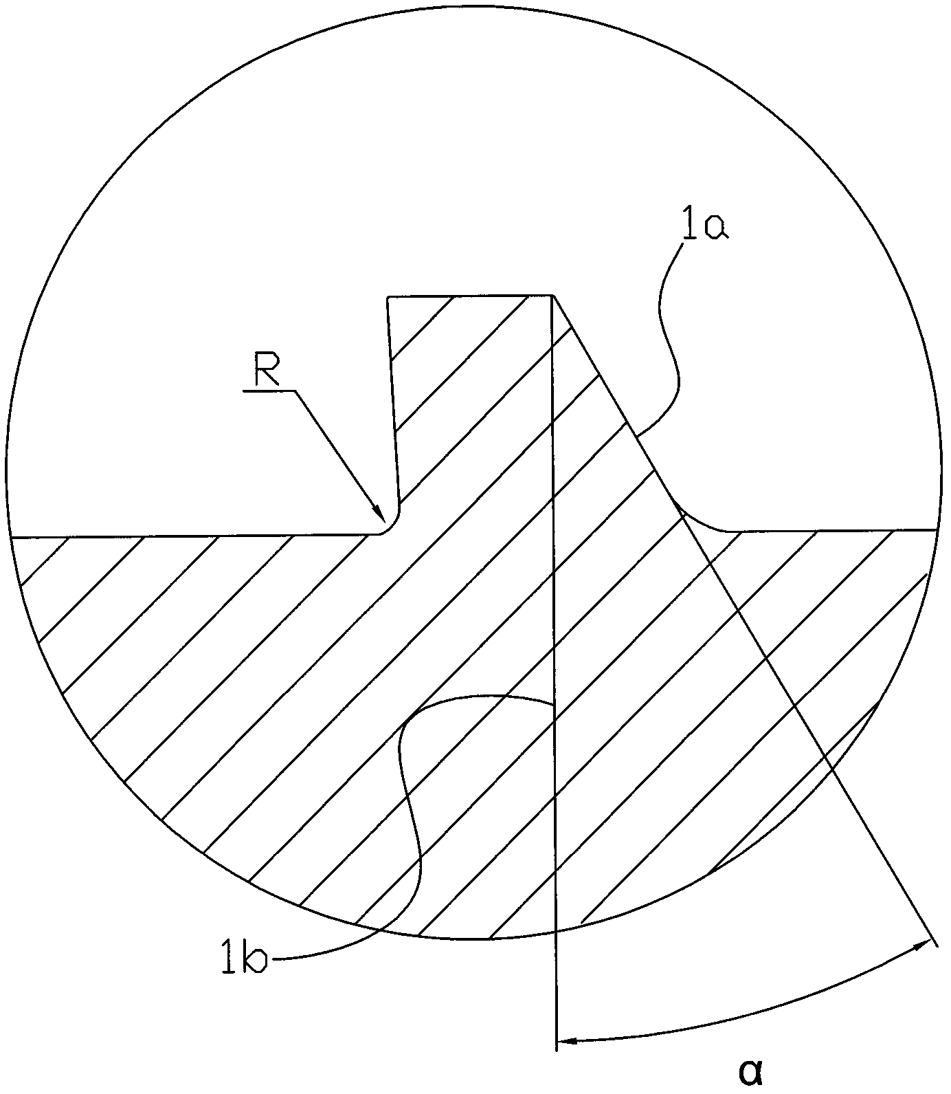
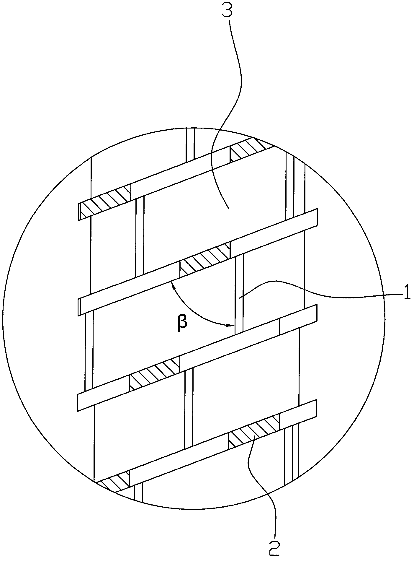
[0020] The present invention will be further described in detail below in conjunction with the accompanying drawings and embodiments.

[0021] Such as Figures 1 to 5 As shown, the extrusion screw has a length-to-diameter ratio of 31:1, including a feed section A, a melting section B, a plasticizing section C, and an extrusion section E. In the feeding section A, the melting section B, and the plasticizing section C. The extrusion section E is provided with screw flights, the screw flights of the plasticizing section C are provided with auxiliary screw flight grooves 2 at intervals, and the screw flights of the plasticizing section C are axially provided with transverse ribs 1, and the transverse ribs 1 and The flight of the plasticizing section C forms several main flight grooves 3 . The thickness of the rib 1 is smaller than the thickness of the screw rib of the plasticizing section C. The angle β formed by the rib 1 and the screw rib of the plasticizing section C is 69°. ...


PUM


Abstract

The invention relates to an extrusion screw, which is characterized in that screw rims are arranged on a charging segment (A), a melting segment (B), a plasticizing segment (C) and an extrusion segment (E). An auxiliary screw rim groove (2) is provided on the screw rim of the plasticizing segment (C) at intervals, a transverse rim (1) is axially provided between the screw rim of the plasticizing segment (C), the transverse rim and the screw rim of the plasticizing segment (C) form a plurality of main screw rim grooves (3). Compared with the prior art, the extrusion screw has the advantages that a main and auxiliary double screw rims structure realizes the separation of a solid phase of the material and a liquid phase of the material, the plasticizing quality can be effectively enhanced, the melt crystallization point can be reduced, and the higher transparent grade of the product is reached; simultaneously, the plasticizing distance and plasticizing time can be shortened, and the shear degradation of highly viscous fluid can be avoided; a protruded nailing block structure of the extrusion segment enables melt to extrude along a netted channel for realizing the stabilization and uniformity of the extrusion of the materials.

Description

technical field [0001] The invention relates to the technical field of manufacturing an injection molding machine, in particular to an extrusion screw in an injection molding machine. Background technique [0002] An existing Chinese utility model patent No. 200920140357.4 titled "Gradient Mixing Screw" discloses a gradual mixing screw whose structure includes a rotating head, a rod body and an external thread, and the rotating head and the rod body are fixed together. There are external threads on the rod body. The end of the rod body close to the rotating head is the feed end, and the other end of the rod body is the discharge end. The rod body is divided into 6 sections. The plasticizing section, the second gradual diameter plasticizing section, the third plasticizing section, the melt mixing section, the foaming agent and material mixing section and the mixture output section. The mixing screw is easy to use and improves the mixing effect of molten materials. However, ...

Claims


Application Information

Patent Timeline
Patent Type & Authority Applications(China)
IPC IPC(8): B29C45/60
Inventor 王成学夏增富邵其艇徐世
Owner 浙江华业塑料机械股份有限公司
Learn More