Garbage feeder

A feeder and garbage technology, applied in conveyors, conveyor objects, conveyor control devices, etc., can solve problems such as breakage, equipment failure, and chain plate conveyor belt 8 impact.

Inactive Publication Date: 2012-06-13
江苏金陵环保科技有限公司
View PDF6 Cites 10 Cited by
  • Summary
  • Abstract
  • Description
  • Claims
  • Application Information

AI Technical Summary

Problems solved by technology

"In conjunction with the attached drawings of this document figure 1 It can be seen that there is a discharge interface 6 between the uniform feeding mechanism and the receiving funnel 7, so there is still a distance between the uniform feeding mechanism and the receiving funnel 7. When the material interface 6 is conveying, when the small garbage bag is higher than the discharge interface 6, it will be blocked at the connection between the discharge end of the material receiving funnel 7 and the inner end of the discharge interface 6, and the uniform feeding mechanism cannot function. Some effects, and the follow-u

Method used


Image

  • Garbage feeder
  • Garbage feeder
  • Garbage feeder

Examples


Embodiment 1)

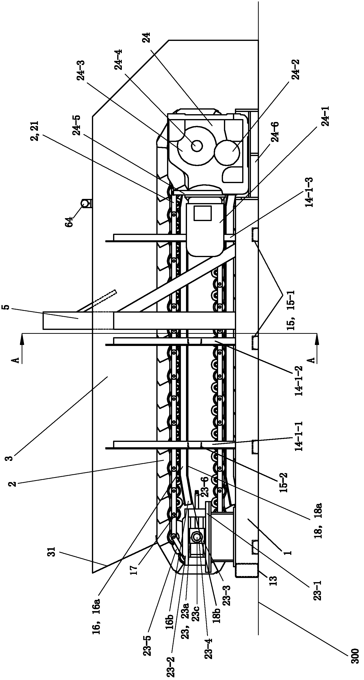
[0075] The description orientation of this embodiment is according to figure 1 The orientation shown is described, figure 1 The up, down, left, and right directions in are the described up, down, left, and right directions. figure 1 The side facing the drawing is the front side, figure 1 The side facing away from the drawing is the rear side. The two sides close to the middle part of the garbage feeder from the front-rear direction are also referred to as inner sides, and the sides farther from the middle part of the garbage feeder from the front-rear direction are called outer sides.

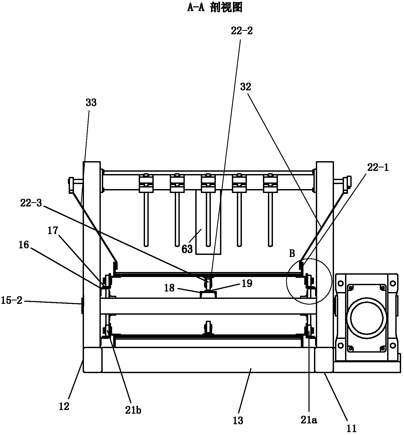
[0076] See figure 1 with Figure 7, The garbage feeder of this embodiment includes a frame 1, a conveying device 2, a material guide trough 3, a uniform material device 5 and a material level feedback device 6. The conveying device 2 is arranged on the frame 1 . Material guide trough 3 is fixed on the frame, and is positioned at conveying device 2 top and right. The uniform material devi...

Embodiment 2)

[0102] See Figure 9 with Figure 10 , the rest of this embodiment is the same as that of Embodiment 1, the difference is that: the supporting column 14 is also provided with connecting plates 14-3, and the number of connecting plates 14-3 is the same as the number of supporting columns 14. Each connecting plate 14-3 is welded and fixed on the upper end surface of the top of the corresponding support column 14 from top to bottom; -3; the rear side plate 33 of the material guide trough 3 is welded and fixed on the connecting plate 14-3 at the top of each rear side support column 14-2.

Embodiment 3)

[0104] See Figure 13 with Figure 14 , The remainder of this embodiment is the same as that of Embodiment 1, except that the garbage feeder of this embodiment is also provided with a receiving hopper 4 and a hopper bracket 7 . The hopper support 7 is arranged on the frame 1 and is positioned at the left part of the frame 1 . The receiving hopper 4 is arranged on the hopper support 7 , located above the left part of the material guide chute 3 , and on the left side of the homogenizing device 5 .

[0105] See Figure 13 with Figure 14 , The hopper bracket 7 includes a set of diagonal braces 71 and a set of frame beams 72 . The diagonal struts 71 are divided into left diagonal struts 71a, front diagonal struts 71b and rear diagonal struts 71c according to their positions. Each diagonal strut 71 is a channel steel, and each diagonal strut 71 is arranged with an outer high and an inner low slope, and the notch faces inward. The inner side of the lower end of each diagonal s...


PUM


Abstract

The invention discloses a garbage feeder, which comprises a machine frame, a conveying device and a guiding tank, wherein the conveying device is arranged on the machine frame; and the guiding tank is fixed on the machine frame and positioned above and on the right side of the conveying device. The garbage feeder is characterized by also comprising a blending device and a feed level feedback device. The machine frame comprises supporting posts, a connecting cross beam and supporting wheel bearers, wherein 1 to 3 supporting wheel bearers are used. Each feeding plate of the conveying device hasa roller support, the number of the roller supports is the same as that of the supporting wheel bearers, and each roller support is rotationally connected with a corresponding supporting roller. The supporting roller of each corresponding feeding plate is contacted with a supporting wheel bearer in a rolling manner. The blending device comprises a main frame body and comb teeth. The comb teeth are arranged on the main frame body. The blending device is arranged in the middle of the left and right direction of the machine frame. The comb teeth are positioned above the conveying device. The feed level feedback device is transversely spun over the guiding tank from the front to the back and is positioned above the part, which is on the right side of the blending device, of the conveying device.

Description

technical field [0001] The invention relates to a domestic garbage processing device, in particular to a garbage feeder capable of uniformly transporting garbage. Background technique [0002] At present, the municipal domestic waste treatment system is set up according to the flow-through treatment of waste. Whether the waste feeding in the waste treatment line is continuous and uniform is related to the operation efficiency of the entire waste treatment system and whether the waste treatment system can operate normally. Garbage treatment lines often use chain plate conveyors or hydraulic reciprocating conveyors as the first equipment on the waste treatment line to solve the problem of intermittent feeding and realize continuous transportation of garbage. However, due to the complex composition of municipal solid waste, the waste is easily tangled and entangled into groups, and the loading equipment such as dump trucks, garbage grabs, loaders, etc. are mostly dumped instant...

Claims


Application Information

Patent Timeline
IPC IPC(8): B65G17/06B65G17/30B65G47/00B65G47/34B65G43/00
Inventor 戴亚南曹成运
Owner 江苏金陵环保科技有限公司
Why Eureka
Try Eureka