
Heat dissipation structure for wind generating set

A technology for wind turbines and heat dissipation structures, applied in wind turbine components, wind turbine combinations, wind turbines, etc., can solve the problems of inability to provide cooling by hot air, radiator failure, seawater corrosion, etc., and achieve stable and reliable cold source. , The cooling effect is stable and the production cost is saved.

Active Publication Date: 2012-06-13
XINJIANG GOLDWIND SCI & TECH
View PDF4 Cites 0 Cited by
  • Summary
  • Abstract
  • Description
  • Claims
  • Application Information

AI Technical Summary

Problems solved by technology

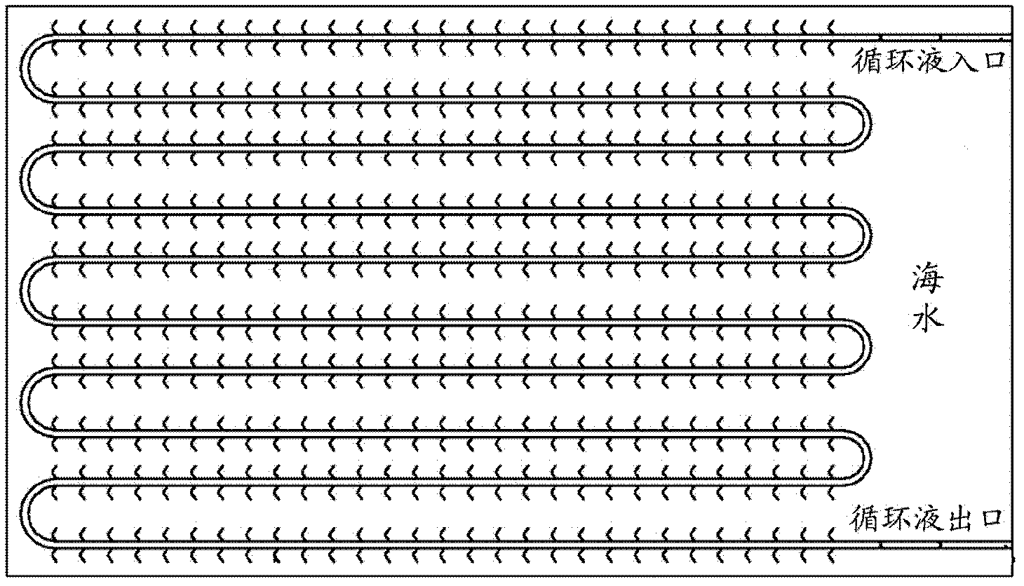
However, this kind of radiator that is only soaked in seawater for heat dissipation has the following problems: although it can avoid the corrosion of the radiator by the salt spray in the air on the sea surface, the seawater itself also has a corrosion effect; in addition, the radiator After soaking in seawater for a long time, microorganisms will be produced on the surface, and these accumulated microorganisms will fill the fins of the radiator. In this case, the radiator that relies on the fins for heat dissipation is basically in a state of failure
However, this heat dissipation method also has defects, that is, because the tower wall can only ensure that it is a complete cold source at night, due to the existence of solar radiation during the day, nearly half of the area of ​​the tower wall will be under solar radiation, and according to Experience in the field, the temperature of the tower wall under solar radiation is very high, in this case the tower wall cannot provide cooling for the hot air flowing through it

Method used


Image

  • Heat dissipation structure for wind generating set
  • Heat dissipation structure for wind generating set
  • Heat dissipation structure for wind generating set

Examples


Embodiment Construction

[0027] Hereinafter, preferred embodiments of the present invention will be described in detail with reference to the drawings. In each of the following embodiments, a wind power generating set with six piles is taken as an example for illustration, but the present invention is not limited thereto, and can be applied to various types of seawater wind generating sets.

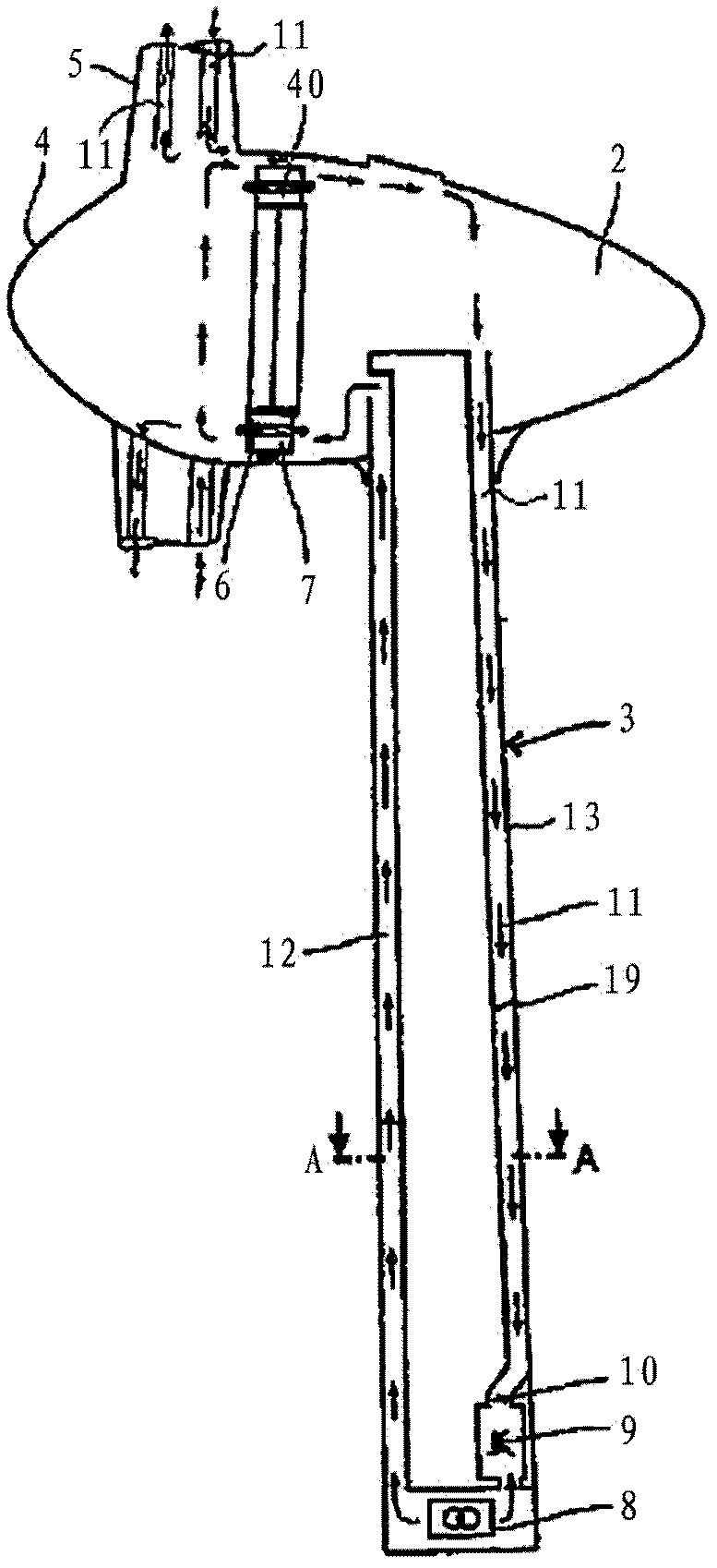
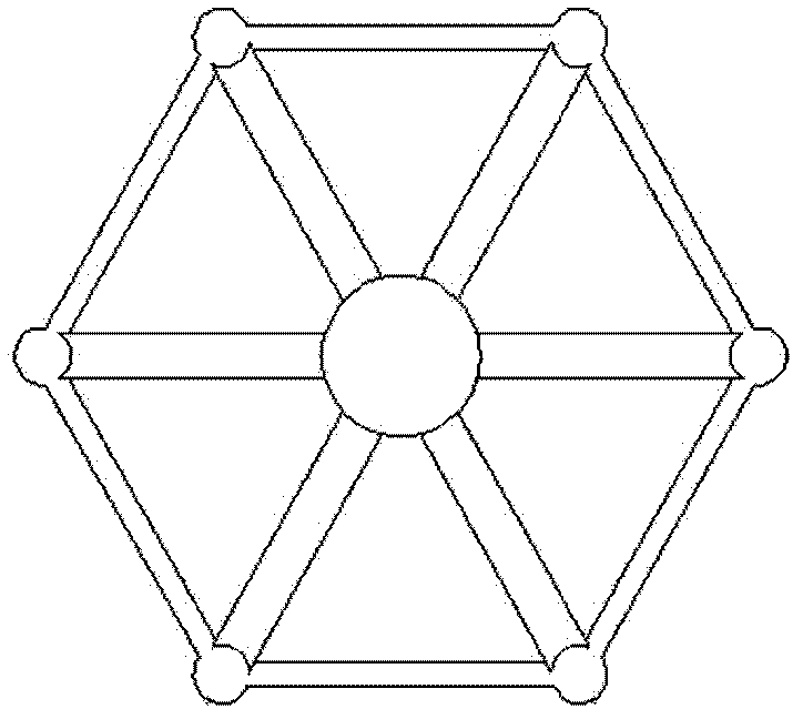
[0028] image 3 is a top view of a wind turbine according to the present invention, Figure 4 for image 3 Partial cutaway view of a wind turbine.

[0029] The wind power generating set according to the present invention generally includes a tower 1 , a support frame 2 , a pile body 3 and a beam 4 . Various electrical equipment (for example, generators, converters, transformers, etc.) are arranged on the inner upper side of the tower 1 . One end of the support frame 2 is connected to the tower tube 1 , and the other end is connected to the pile body 3 , and each support frame 2 forms an inclined state to supp...


PUM


Abstract

The invention relates to a heat dissipation structure for a wind generating set. The heat dissipation structure is characterized by comprising at least one tower in which multiple sets of electrical equipment is arranged, and at least one pile shaft for supporting the at least one tower, wherein the interior of the tower is divided by a partition plate so as to form a tower air supply channel and a tower air return channel; and a pile shaft air supply channel and a pile shaft air return channel which are communicated with the tower air supply channel and the tower air return channel are formed in the pile shaft; and the pile shaft air supply channel and the pile shaft air return channel are communicated with each other only at the bottom of the pile shaft.

Description

technical field [0001] The present invention relates to a heat dissipation structure of a wind power generating set capable of stably cooling. Background technique [0002] With the rise of wind turbines, wind turbine manufacturers are paying more and more attention to the influence of the surrounding environment where the wind turbines are installed on the turbines. For example, in a wind turbine installed in the ocean, how to avoid the corrosion of the internal equipment of the unit by the corrosive air containing salt mist on the sea surface, and how to solve the problem of relatively high relative humidity of the air on the sea surface, which is the adverse effect of the marine environment on the wind turbine, However, the marine environment also has its usable side. In addition to the abundant offshore wind resources, the characteristics of seawater’s large heat storage capacity determine that the seawater temperature changes within a small range throughout the year. Th...

Claims


Application Information

Patent Timeline
Patent Type & Authority Applications(China)
IPC IPC(8): F03D11/00F03D11/04F03D9/00F03D13/20F03D80/60
CPCY02E10/728Y02E10/72
Inventor 吴立洲张新刚
Owner XINJIANG GOLDWIND SCI & TECH
Learn More