Static-pressure gas bearing

A technology of floating bearings and bearings, applied in bearings, shafts and bearings, mechanical equipment, etc., can solve problems such as rubbing and vibration, solid locking, and rotors that cannot be balanced and floated

Active Publication Date: 2012-06-13
保山鑫隆电子科技有限公司
View PDF4 Cites 9 Cited by
  • Summary
  • Abstract
  • Description
  • Claims
  • Application Information

AI Technical Summary

Problems solved by technology

[0004] In the traditional static pressure air bearing, because the gas is continuously discharged from the outer edge of the bearing into the atmosphere, the air does not have boundary lubrication ability. During the working process, if the air bearing load exceeds the specified limit, direct contact with solids will occur immediately. And locked, resulting in damage to the bearing and the main shaft, and it can only bear radial load, it can not meet the requirements for the situation of both radial load and axial load
In addition, since the air contains particles, powder layers and other particles, when the air is pressed into the gap between the bearings, these particles are easy to deposit around the gas injection hole, and after a long time, the gas injection hole will be blocked, so that the gas cannot reach the bearing and the rotor smoothly. In between, the rotor cannot be balanced and floated, resulting in serious rubbing and vibration. When the rotor vibrates or local rubbing or external disturbance, the air pressure effect at both ends of the rotor is no longer equal, thus reducing the static pressure air bearing. load carrying capacity, which reduces the reliability of high-speed rotating machinery

Method used


Image

  • Static-pressure gas bearing
  • Static-pressure gas bearing

Examples


Embodiment Construction

[0015] The present invention will be further described below in conjunction with specific drawings and embodiments.

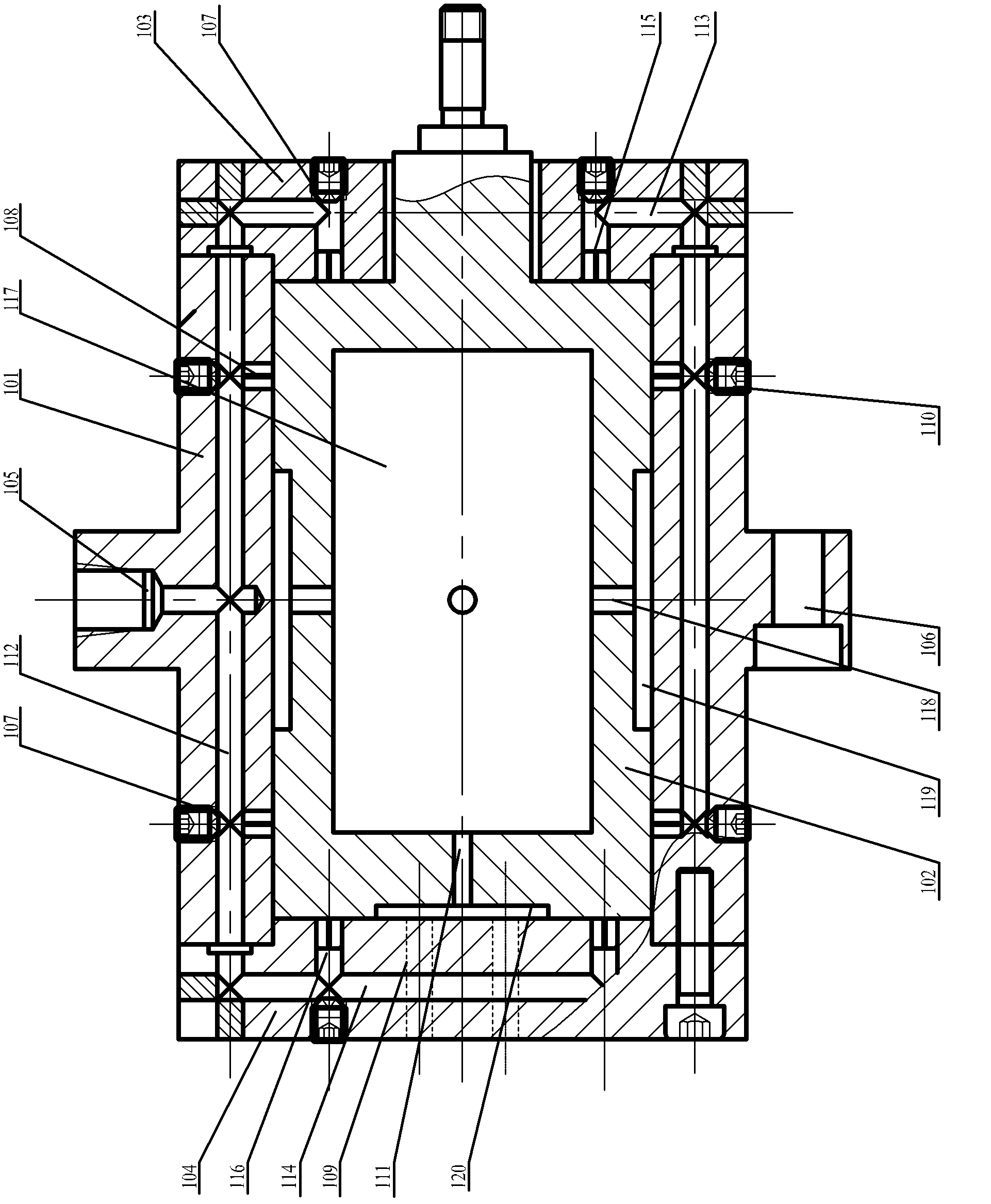
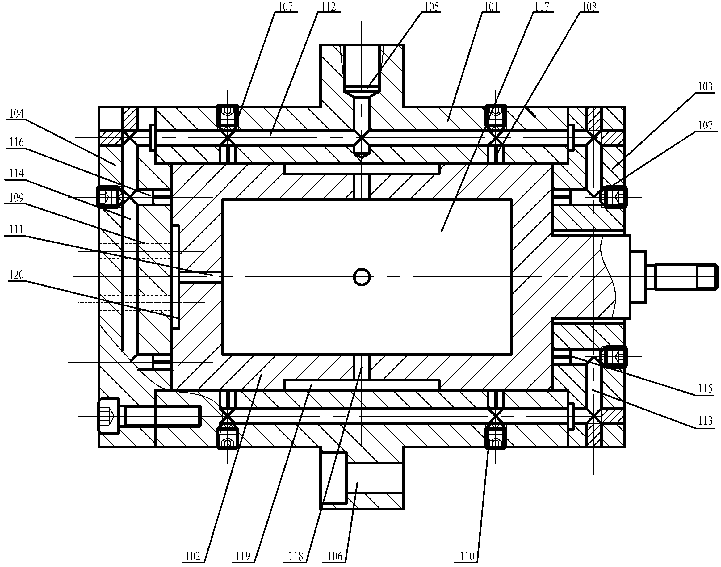
[0016] As shown in the figure, the present invention mainly consists of a bearing main body 101, a rotor 102, a front cover 103, a rear cover 104, an air inlet 105, a fixing hole 106, a threaded hole 107, a main body jet hole 108, an air outlet 109, a screw 110, a shaft Air outlet hole 111, main body air chamber 112, front cover air chamber 113, rear cover air chamber 114, front cover air injection hole 115, rear cover air injection hole 116, rotor air chamber 117, radial air outlet hole 118, circular groove 119 and Circular concave groove 120 and other components constitute.

[0017] The static pressure air bearing includes a cylindrical bearing main body 101, a rotor 102 is installed in rotation in the bearing main body 101, a front cover 103 is fixed on the right shaft end of the bearing main body 101, and a left side shaft end of the bearing main body 101 ...


PUM


Abstract

The invention relates to a static-pressure gas bearing comprising a cylindrical bearing body, a rotor rotatably arranged in the bearing body, a front cap fixed on a right side of the bearing body, and a back cap fixed on a left side of the bearing body. Threaded holes arranged coaxially with a back cap gas-ejection hole are provided on the back cap on the left of a back cap gas chamber. Gas outlets are arranged in the back cap along an axial direction of the back cap. Each threaded hole is provided with a screw. A rotor gas chamber is provided in the rotor. Radial gas outlets are arranged in the rotor along a radial direction of the rotor. An annular groove is provided on a peripheral wall of the rotor. An axial gas outlet is arranged on a left end of the rotor along an axial direction ofthe rotor. A round recess is provided on the left end-face of the rotor. During an operation process of a traditional gas bearing, only a radial air film is provided, direct contact of boundary solids can easily happen, and locking is caused, such that the bearing and a main shaft might be damaged. With the static-pressure gas bearing provided by the invention, the problem can be solved, and the bearing can work under both a radial load and an axial load.

Description

technical field [0001] The invention relates to the technical field of high-speed rotary machinery and ultra-precision instruments, and discloses a static pressure air bearing. Background technique [0002] The air bearing is a bearing that uses the viscosity of the gas to increase the pressure of the gas in the gap to suspend the shaft. It is a high-tech product developed rapidly in the middle of the 20th century. Air bearings rely on air lubrication. Compared with conventional oil-lubricated bearings (rolling bearings or oil-based sliding bearings), it has many good characteristics: the friction factor and friction torque are small, and the gas bearing can work in the cleanest state. It has the characteristics of cold working, the motion wear rate is almost zero, low noise, small vibration, high precision, long life, can work in a wide temperature range and harsh environment, and can maintain a small gap. Therefore, it is widely used in national defense, energy, machine t...

Claims


Application Information

Patent Timeline
Patent Type & Authority Applications(China)
IPC IPC(8): F16C32/06
Inventor 柳祝平黄小卫王静
Owner 保山鑫隆电子科技有限公司
Why Eureka
Try Eureka