Hydraulic transmission system and reversing valve thereof

A hydraulic reversing valve and reversing valve technology, applied in the hydraulic field, can solve the problems of difficult operation of reversing valves, large space occupation, complicated layout, etc., and achieve the effects of simple structure, small occupation space and low operation difficulty.

Active Publication Date: 2012-06-13
SANY AUTOMOBILE MFG CO LTD
View PDF8 Cites 0 Cited by
  • Summary
  • Abstract
  • Description
  • Claims
  • Application Information

AI Technical Summary

Problems solved by technology

Multiple reversing valves are not only difficult to operate, but also have a complex layout and take up a lot o

Method used


Image

  • Hydraulic transmission system and reversing valve thereof
  • Hydraulic transmission system and reversing valve thereof
  • Hydraulic transmission system and reversing valve thereof

Examples


Embodiment Construction

[0024] The core of the present invention is to provide a reversing valve of a hydraulic transmission system, which can realize the purpose of multi-position and multi-way when used alone, so as to meet the needs of engineering practice, and its structure is relatively simple, the operation difficulty is low, and the occupied space is small . Another core of the present invention is to provide a hydraulic transmission system including the above-mentioned reversing valve.

[0025] In order to enable those skilled in the art to better understand the technical solutions of the present invention, the present invention will be further described in detail below in conjunction with the accompanying drawings and specific embodiments.

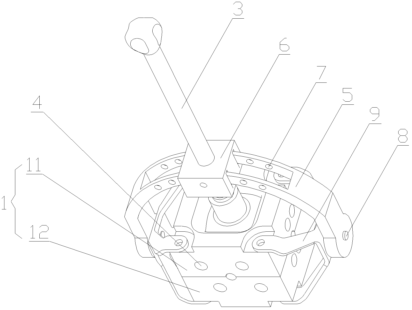
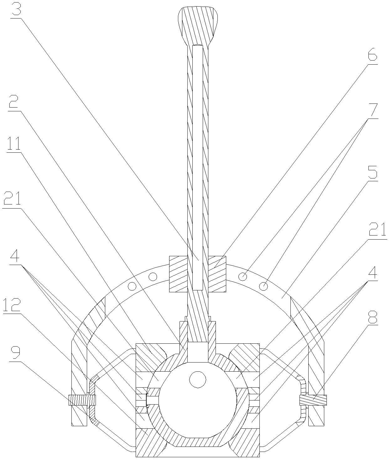
[0026] Please refer to figure 1 with figure 2 , figure 1 A perspective view of a specific embodiment of the reversing valve provided by the present invention; figure 2 for figure 1 Cutaway view of the directional valve shown.

[0027] In a specif...


PUM


Abstract

The invention discloses a hydraulic reversing valve, which comprises a valve body (1), a valve core (2) arranged in the valve body (1) in a rotatable manner and an operating rod (3) for driving the valve core (2) to rotate in the valve body (1), wherein a hollow cavity and at least three first oil feed holes (21) are formed in the valve core (2); at least two second oil feed holes (4) are formed in the valve body; and any one of the first oil feed holes is selectively connected with or disconnected from any one of the second oil feed holes (4) through rotation of the valve core (2). The operating rod drives the valve core to move, so that switching among at least six oil paths is realized, and the structure is simple. The invention also discloses a hydraulic transmission system comprisingthe reversing valve.

Description

technical field [0001] The invention relates to the field of hydraulic technology, in particular to a reversing valve used in a hydraulic transmission system. The present invention also relates to a hydraulic transmission system comprising the above-mentioned reversing valve. Background technique [0002] Hydraulic transmission is a transmission method that uses liquid as the working medium to transmit energy and control. Hydraulic transmission has the advantages of simple structure, large output power, and easy realization of frequent reversing, and is widely used in various fields of production and life. [0003] The hydraulic transmission system mainly includes power components such as hydraulic pumps, actuators such as hydraulic cylinders or hydraulic motors, control components such as directional control valves, and auxiliary components such as fuel tanks. It is used to convert the hydraulic energy of the pressure oil into mechanical energy, and the control element is ...

Claims


Application Information

Patent Timeline
IPC IPC(8): F16K11/08F16K31/60
Inventor 夏浩文程建群邓云海
Owner SANY AUTOMOBILE MFG CO LTD
Why Eureka
Try Eureka