Moving magnet type linear rotation two-degree-of-freedom motor

A degree of freedom and moving magnet technology, applied in the direction of electromechanical devices, electrical components, electric components, etc., can solve problems such as large noise, large volume, and poor smoothness of motion

Active Publication Date: 2012-06-13
HARBIN INST OF TECH SHENZHEN GRADUATE SCHOOL +1
View PDF7 Cites 29 Cited by
  • Summary
  • Abstract
  • Description
  • Claims
  • Application Information

AI Technical Summary

Problems solved by technology

Chinese patent "201020582357, High Frequency Linear Rotating Motor" The linear rotating motor is essentially just two single-degree-of-freedom motors installed together, not a real integrated linear rotating two-degree-of-freedom motor, and the volume is still large
Linear rotary stepper motors generally adopt open-loop control, so the motion accuracy is relatively low
Linear rotary stepper motors have step angle and step distance, which are not suitable for high-response motion occasions with micro strokes, and the smoothness of motion is worse than that of electromagnetic motors, which is prone to step loss and overshoot
When moving at low speed, there is vibration and noise

Method used


Image

  • Moving magnet type linear rotation two-degree-of-freedom motor
  • Moving magnet type linear rotation two-degree-of-freedom motor
  • Moving magnet type linear rotation two-degree-of-freedom motor

Examples


Embodiment Construction

[0028] The present invention will be further described below in conjunction with the description of the drawings and the specific embodiments.

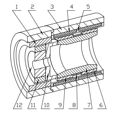
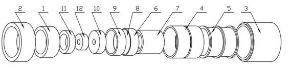
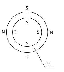
[0029] Figure 1 to Figure 7 The reference numerals in the middle are: front winding 1; front yoke 2; rear yoke 3; rear winding 4; winding support seat 5; rear magnetic ring 6; inner yoke 7; positioning ring 8; middle magnetic ring 9; Magnetic base 10; front magnetic ring 11; iron core 12.

[0030] Such as Figure 1 to Figure 7 As shown, a moving magnet linear rotation two-degree-of-freedom motor includes a ring-shaped and coaxially mounted mover and a stator. The stator includes a ring-shaped and coaxially mounted front yoke 2 and a rear yoke 3 , The winding support seat 5, the front winding 1 and the rear winding 4, one end of the front yoke 2 is connected to one end of the rear yoke 3, and the front winding 1 is sleeved inside the front yoke 2, The rear winding 4 is sleeved between the outer side of the winding support base 5 and the...


PUM


Abstract

The invention relates to a moving magnet type linear rotation two-degree-of-freedom motor. The moving magnet type linear rotation two-degree-of-freedom motor comprises a rotor and a stator. The stator comprises a circular front magnet yoke, a back magnet yoke, a winding support, a front winding and a back winding, wherein one end of the front magnet yoke is connected with one end of the back magnet yoke; the front winding is sleeved on the inner side of the front magnet yoke; and the back winding is sleeved between the outer side of the winding support and the inner side of the back magnet yoke. The rotor comprises a permanent magnet, an iron core, an inner magnet yoke, a magnet isolating seat and a positioning ring, wherein the permanent magnet comprises a front magnet ring, a middle magnet ring and a back magnet ring; and the front magnet ring is sleeved between the inner side of the front winding and the outer side of the iron core. The invention has the advantages that: the rotor can be driven to do rotary motion by the front winding and also can be driven to do linear motion by the back winding, and the two-degree-of-freedom composite motion of the rotary motion and the linear motion can be output by one motor.

Description

Technical field [0001] The invention relates to a motor, in particular to a moving magnet type linear rotation motor with two degrees of freedom in the motor. Background technique [0002] Existing motors generally can only provide single-degree-of-freedom rotary motion (such as a rotary motor) or linear motion (such as a linear motor), but cannot provide a compound motion that combines both rotary motion and linear motion. However, in the fields of medical treatment, semiconductor packaging, aviation, etc., there are a large number of requirements for two-degree-of-freedom linear and rotational compound motion, and the motion drive components are required to be small in size and light in weight. The traditional implementation scheme is to establish two independent motor systems and their transmission devices to drive linear and rotary motions respectively. The system is large in size and slow in response. The rapid development of modern industry has put forward higher and more ...

Claims


Application Information

Patent Timeline
Patent Type & Authority Applications(China)
IPC IPC(8): H02K41/00H02K41/02H02K41/06
Inventor 楼云江赵学超黄瑞宁
Owner HARBIN INST OF TECH SHENZHEN GRADUATE SCHOOL
Why Eureka
Try Eureka