Radial-array permanent-magnet eddy current retarder

A permanent magnet eddy current and retarder technology, applied in the direction of permanent magnet clutches/brakes, etc., can solve the problems of low utilization rate of permanent magnets and unusable magnetic fields, etc., and achieve the effects of easy transmission, good heat dissipation conditions and high reliability

Inactive Publication Date: 2012-06-13
ZHEJIANG UNIV
View PDF9 Cites 15 Cited by
  • Summary
  • Abstract
  • Description
  • Claims
  • Application Information

AI Technical Summary

Problems solved by technology

They all only use the magnetic field on one side of the permanent magnet ring for eddy current braking, and the other side is the mounting surface, so the magnetic field on this side cannot be used. Therefore, the utilization rate of the permanent magnet is very low.

Method used


Image

  • Radial-array permanent-magnet eddy current retarder
  • Radial-array permanent-magnet eddy current retarder
  • Radial-array permanent-magnet eddy current retarder

Examples


Embodiment Construction

[0022] The present invention will be further described below in conjunction with the accompanying drawings and embodiments.

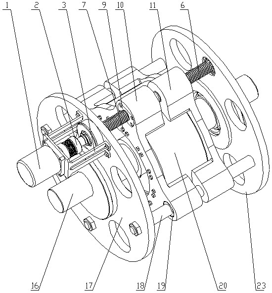
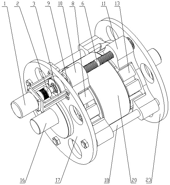
[0023] Such as figure 2 , image 3 , Figure 4 , Figure 5 As shown, a radial array permanent magnet eddy current retarder includes a left fixed plate 17, a right fixed plate 23, a transmission shaft 16, a rotor 20, a servo motor 1, a coupling 2, a motor fixing frame 3, two-way wire The lever shaft 6, the opposite left and right lead screw nuts 9,12, three linear optical axes 18, two stators with the same structure. The rotor 20 made of magnetically conductive material is installed on the drive shaft 16 through a key. One end of the rotor 20 rests on the shaft shoulder, and the other end is fixed with a round nut 22; the outer ring of the rotor 20 has two symmetrical annular grooves, and the inner ring groove 1. The outer cylindrical surface constitutes the working surface of the rotor 20; the web between the rotor hub and the outer ring of the rot...


PUM


Abstract

The invention discloses a radial-array permanent-magnet eddy current retarder. Rotors are installed on a transmission shaft; the transmission shaft is installed in a central hole of a fixing plate; two ends of a bidirectional screw shaft are installed inside holes above the central hole of the fixing plate; two ends of each of three linear optical shafts are fixed into holes in front of, behind and below the central hole of the fixing plate; each of the two rotors consists of a radial-array permanent-magnet ring and a retaining rack; an end surface of one side of the permanent-magnet ring is fixed on an end surface of the retaining rack through bolts; radial clearances are formed between an inner cylindrical surface and an outer cylindrical surface of the permanent-magnet ring and an inner cylindrical surface and an outer cylindrical surface of an annular groove of each rotor; four installing holes are uniformly distributed on the retaining rack; an upper installing hole is matched with the bidirectional screw shaft through a screw nut; the other three installing holes are matched with the linear optical shafts through linear bearings; and a servo motor is connected whit the bidirectional screw shaft through a shaft coupler. In the radial-array permanent-magnet eddy current retarder, the utilization ratio of a magnet is high, the brake moment is large, the response is quick, and the stepless regulation of the brake moment is realized.

Description

technical field [0001] The invention relates to an auxiliary braking device for vehicles, in particular to a radial array permanent magnet eddy current retarder. Background technique [0002] At present, the retarders used in vehicles at home and abroad mainly include hydraulic retarders and eddy current retarders. The eddy current retarders are generally composed of stators, rotors, coils for generating magnetic fields, and fixed brackets. [0003] When the eddy current retarder is working, the electromagnetic coil is energized to generate a magnetic field, and the magnetic flux in the area surrounded by countless closed wires inside the working surface where the rotating rotor cuts the magnetic force line changes, thereby generating a vortex-shaped induced current on the rotor working surface. That is, the eddy current. After the eddy current is generated, the electromagnetic field will produce resistance to the charged rotor to prevent the rotor from rotating, that is, th...

Claims


Application Information

Patent Timeline
Patent Type & Authority Applications(China)
IPC IPC(8): H02K49/10
Inventor 魏燕定郭远晶周晓军魏春雨罗竹辉余小勇
Owner ZHEJIANG UNIV
Why Eureka
Try Eureka