Single-end forward power inverter

A forward converter, single-ended technology, applied in the direction of converting DC power input to DC power output, output power conversion devices, instruments, etc., can solve the problem that the secondary side diode circuit cannot be used

Inactive Publication Date: 2012-06-13
BEIJING SUPLET +1
View PDF10 Cites 19 Cited by
  • Summary
  • Abstract
  • Description
  • Claims
  • Application Information

AI Technical Summary

Problems solved by technology

[0004] At present, there is already a clamping circuit technology on the secondary side of the transformer. This technology can only solve the magnetic reset problem of the cir...

Method used


Image

  • Single-end forward power inverter
  • Single-end forward power inverter
  • Single-end forward power inverter

Examples


Embodiment 1

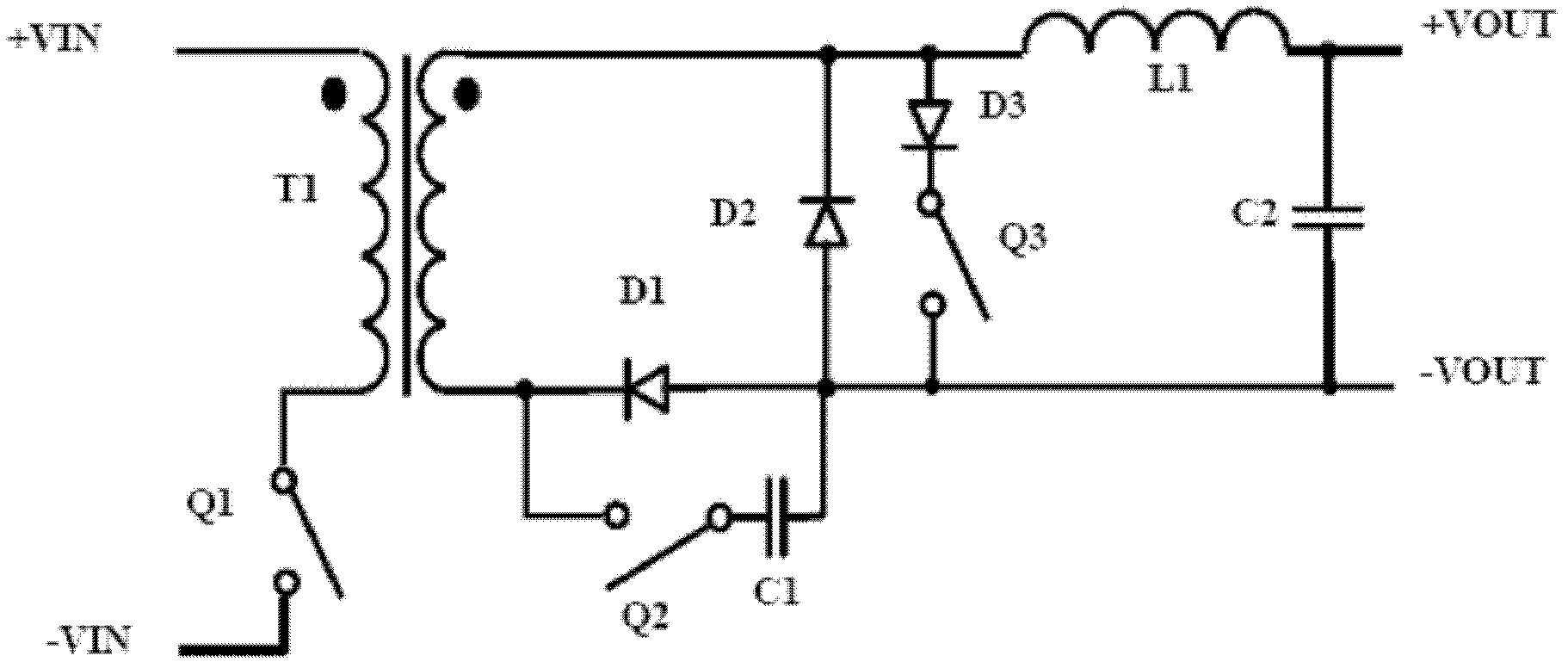
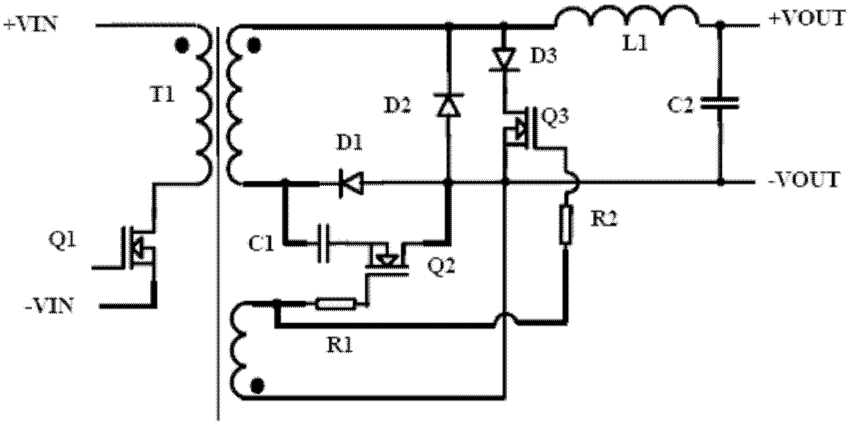
[0029] figure 2 The specific circuit schematic diagram of the single-ended forward converter provided by this embodiment is shown, as figure 2 As shown, in this embodiment, both the clamp transistor Q2 and the discharge transistor Q3 are NMOS transistors.

[0030] figure 2 neutralize figure 1 The same components and connection relationship in the above will not be repeated here, and only the connection relationship of the components related to the clamping tube Q2 and the discharge tube Q3 will be described.

[0031] The source of the clamping tube Q2 is connected to one end of the clamping capacitor C1, and the other end of the clamping capacitor C1 is connected to the cathode of the rectifier tube D1, and the gate of the clamping tube Q2 is connected to the differential voltage of the auxiliary winding of the transformer T through the resistor R1 Famous end.

[0032] The source of the discharge tube Q3 is connected to the anode of the freewheeling tube D2, the drain o...

Embodiment 2

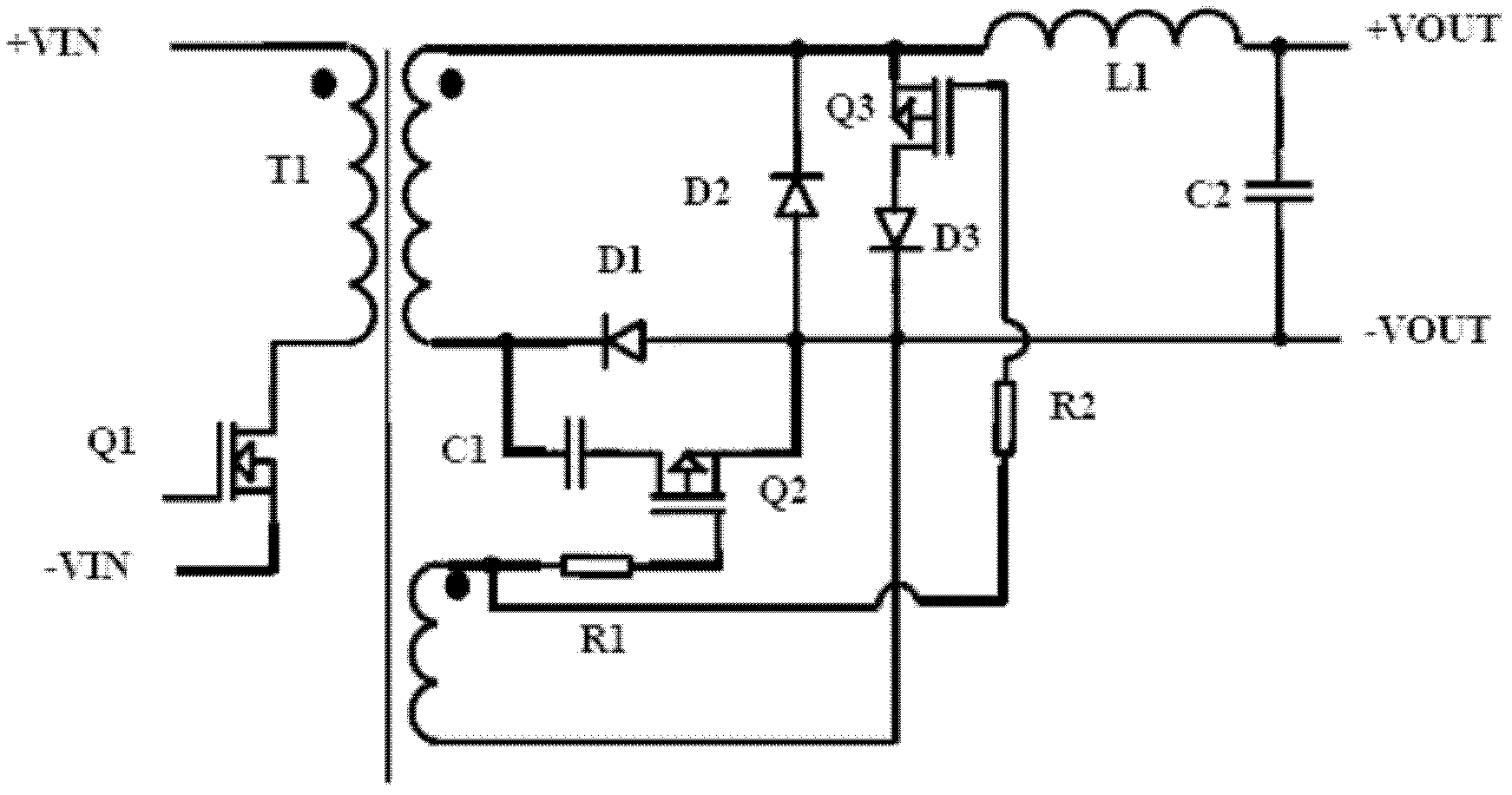
[0039] image 3 A specific circuit diagram of a single-ended forward converter provided in this embodiment is shown, as shown in image 3 As shown, in this embodiment, both the clamp transistor Q2 and the discharge transistor Q3 are PMOS transistors.

[0040] image 3 neutralize figure 1 The same components and connection relationship in the above will not be repeated here, and only the components and connection relationship related to the clamping tube Q2 and the discharge tube Q3 will be described.

[0041] The drain of the clamping transistor Q2 is connected to one end of the clamping capacitor C1, and the other end of the clamping capacitor C1 is connected to the cathode of the rectifier D1. Therefore, the drain of the clamping tube Q2 is connected to the opposite end of the secondary winding of the transformer T.

[0042] The source of the clamping tube Q2 is connected to the anode of the rectifier D1, so the source of the clamping tube Q2 is also connected to the outpu...


PUM


Abstract

The embodiment of the invention provides a single-end forward power inverter, comprising a transformer T, a primary side switching tube Q1, a rectification filtering module and a clamping module. The rectification filtering module comprises a rectifier tube D1, an afterflow tube D2, a filter inductor L and a filter capacitor C2; the clamping module comprises a clamping tube Q2, a clamping capacitor C1, a discharging tube Q3 and a discharging backward diode D3, a serial branch consisting of the clamping tube Q2 and the clamping capacitor C1 is connected with two ends of the rectifier tube D1 in parallel, and a serial branch consisting of the discharging tube Q3 and the discharging backward diode D3 is connected with two ends of the afterflow tube D2 in parallel; and the clamping tube Q2 is reversely switched on and off with the discharging tube Q3 and the primary side switching tube Q1.

Description

technical field [0001] The invention belongs to the technical field of high-frequency switches, in particular to a single-end forward power converter. Background technique [0002] The single-ended forward circuit structure is the most common technology in the field of small and medium power high-frequency switching power supply technology. Its circuit is simple and reliable, and the magnetic components are small in size and easy to design. When the primary switch is turned on, the input power transmits energy to the load through the transformer, and at the same time, the excitation current of the transformer reaches the maximum value. Since the excitation current cannot be transmitted to the secondary side through the transformer, it is necessary to increase the excitation current reset circuit, otherwise the transformer will be saturated, that is, the magnetic reset circuit needs to be added. [0003] The clamp technology is the most reliable technology with the highest c...

Claims


Application Information

Patent Timeline
IPC IPC(8): H02M3/335
Inventor 金祖敏王丹
Owner BEIJING SUPLET
Why Eureka
Try Eureka