Novel camera locating tracking method for intelligent automatic sound mixing system and device thereof

A positioning tracking and automatic technology, applied in stereo systems, two-way working systems, quasi-stereo systems, etc., to meet the requirements of use, easy to operate, and flexible to use.

Inactive Publication Date: 2012-06-13
天津市华音宇科工贸有限公司
View PDF6 Cites 0 Cited by
  • Summary
  • Abstract
  • Description
  • Claims
  • Application Information

AI Technical Summary

Problems solved by technology

[0003] See attached figure 1 The working principle of the existing intelligent automatic mixing equipment with camera positioning and tracking function is: the audio signal from each microphone is converted into a level signal by the input amplifier and then sent to the signal comparator to compare with the audio signal. When it is greater than the threshold level of the noise gate, the signal can reach the input terminal of the "maximum value comparator"; in the "maximum value comparator", the N signals from the entrance are electrically Comparing the magnitude of the flat amplitude, only the one with the largest level among the N signals at the entrance is output to the output amplifier to the post-stage sound reinforcement equipment to achieve sound reinforcement; at the same time, it provides a driving signal to the camera driver to align the camera The speaker makes the image of the speaker displayed on the projection screen; it can be seen that the position of the camera positioning tracking display image is controlled by the

Method used


Image

  • Novel camera locating tracking method for intelligent automatic sound mixing system and device thereof
  • Novel camera locating tracking method for intelligent automatic sound mixing system and device thereof
  • Novel camera locating tracking method for intelligent automatic sound mixing system and device thereof

Examples


Embodiment Construction

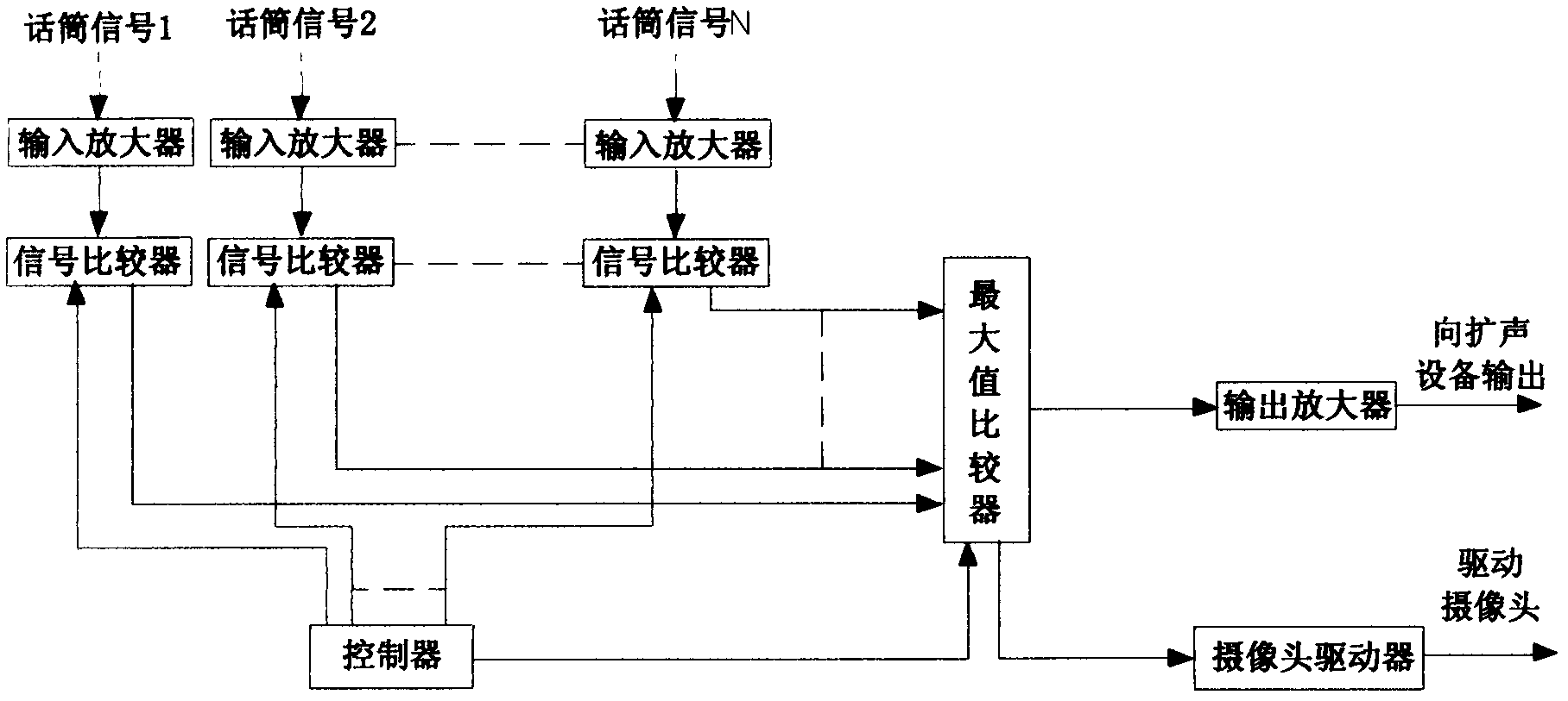
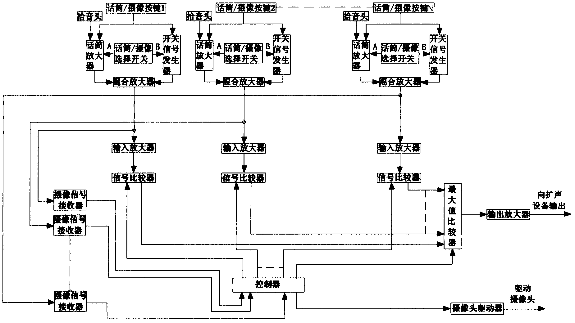
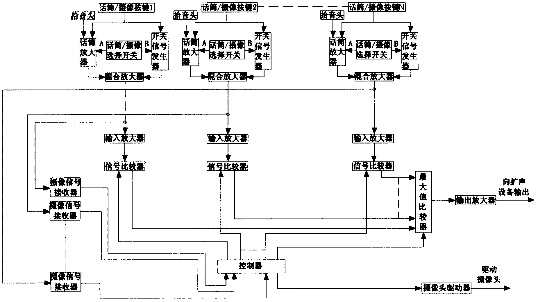
[0015] Refer to the attached figure 2 , further describe the present invention:

[0016] The new camera positioning and tracking method of the intelligent automatic sound mixing system mainly includes the following steps:

[0017] 1) The audio signal and camera signal are controlled separately, and the microphone channel and camera channel are designed separately. The microphone channel is composed of a pickup head for receiving audio signals, a microphone amplifier for amplifying audio signals, and a mixing amplifier for receiving signals; the camera channel is composed of a sending The switch signal generator of the camera request signal is composed of a mixed amplifier for receiving the signal; it is characterized in that: a microphone / camera button is designed on the upper end of the microphone channel and the camera channel to control the opening or closing of the microphone and the camera request signal respectively; A microphone / camera selection switch is also designe...


PUM


Abstract

A novel camera locating tracking method for an intelligent automatic sound mixing system mainly includes following steps: (1) controlling audio signals and camera signals separately and designing a microphone channel and a camera channel respectively, wherein the microphone channel and the camera channel are characterized in that microphone/camera keys are arranged at the upper ends of the microphone channel and the camera channel, and a microphone/camera selecting switch is further arranged between the microphone channel and the camera channel; (2) designing a camera signal receiver for receiving camera request signals, enabling the camera signal receiver to be connected with a mixing amplifier and a controller in the intelligent automatic sound mixing system, enabling the controller to provide signals for a camera driver and control position transition of a camera; and (3) connecting the mixing amplifier and an input amplifier in the intelligent automatic sound mixing system, and enabling the audio signals to achieve sound amplification according to the working principle of intelligent automatic sound mixing. A phenomenon that projection images run along with variation of sound amplifying signals caused by providing the driving signals for the camera driver through the sound amplifying signals is changed thoroughly.

Description

technical field [0001] The invention belongs to the technical field of audio equipment, in particular to audio equipment dedicated to speech sound reinforcement systems. Background technique [0002] At present, intelligent automatic sound mixing equipment with camera positioning tracking function is often used in language sound reinforcement systems. The effect is that when the speaker is speaking, the camera positioning tracking function can project the image of the speaker to the projection screen at the same time In addition, participants in different positions can clearly see the speaker through the projection screen, achieving a good conference effect of sound and visual communication, which is deeply loved by users. [0003] See attached figure 1 The working principle of the existing intelligent automatic mixing equipment with camera positioning and tracking function is: the audio signal from each microphone is converted into a level signal by the input amplifier and...

Claims


Application Information

Patent Timeline
IPC IPC(8): H04N7/14H04N5/232H04S5/00
Inventor 叶晓钟谷丰彭明陈湘林孙洁
Owner 天津市华音宇科工贸有限公司
Why Eureka
Try Eureka