NdFeB sintered magnet production method and production device, and NdFeB sintered magnet produced with said production method

A technology of sintered magnets and manufacturing methods, which is applied in the manufacture of inductors/transformers/magnets, magnetic materials, magnetic objects, etc., can solve the problems of demagnetization curve squareness, magnetic properties, material utilization efficiency, and manufacturing costs. Effects of residual magnetic flux density, easy handling, and low-cost manufacturing

Inactive Publication Date: 2012-06-13
INTER METALLICS KK
View PDF11 Cites 15 Cited by
  • Summary
  • Abstract
  • Description
  • Claims
  • Application Information

AI Technical Summary

Problems solved by technology

However, the chips generated in the cutting process cannot be reused as magnets, which reduces the utilization efficiency of materials and increases the production cost.
In addition, the mechanical damage caused by cutting makes the squareness of the demagnetization curve (H K / H CJ ) and other problems of magnetic property degradation also exist

Method used


Image

  • NdFeB sintered magnet production method and production device, and NdFeB sintered magnet produced with said production method
  • NdFeB sintered magnet production method and production device, and NdFeB sintered magnet produced with said production method
  • NdFeB sintered magnet production method and production device, and NdFeB sintered magnet produced with said production method

Examples


Embodiment

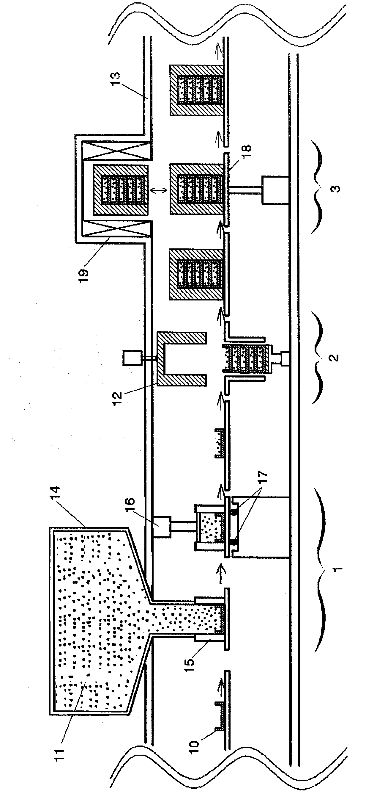
[0067] use Figure 5 and Figure 6 The first embodiment of the manufacturing apparatus of the NdFeB-based sintered magnet of the present invention will be described. The basic structure of the device and figure 1 have the same structure, but differ in that the orientation part 3 is provided with an induction heating coil 20 for heating the alloy powder 11 together with the mold 10 . In the sintered magnet manufacturing apparatus of this embodiment, the mold 10 is inserted inside the induction heating coil 20 , and an electric current is supplied to the induction heating coil 20 to heat the alloy powder 11 together with the mold 10 . Since the induction heating coil 20 is arranged above the conveyance line so that its central axis coincides with the central axis of the magnetic field applying coil 19, heating and magnetic field application can be continuously performed only by moving the elevating platform 18 up and down.

[0068] In addition, the heating method is not limit...


PUM

PropertyMeasurementUnit
densityaaaaaaaaaa
strengthaaaaaaaaaa
strengthaaaaaaaaaa

Abstract

Disclosed are a production method and production device for producing a thin-shaped NdFeB sintered magnet with superior magnetic properties, particularly coercive force and degree of orientation, and an NdFeB sintered magnet produced with said production method and production device. The NdFeB sintered magnet production device is provided with a filling unit (1) that supplies an alloy powder (11) comprising a prescribed amount of Dy to molds (10) and fills the powder to a density in the range of 3.0 to 4.2 g/cm3, an orienting unit (3) that orients the molds (10) filled with the alloy powder (11) in a magnetic field, a sintering furnace (not shown) that with each mold (10) sinters the alloy powder (11) within the molds (10) that have been oriented by the orienting unit (3), and a conveying unit that comprises a belt conveyor and a manipulator (not shown) and conveys the molds (10); to each unit and the sintering furnace. The production device is also provided with coils for thermal orientation (20) that reduce the coercive force of each particle in the alloy powder (11) by heating the alloy powder (11) filled within the molds (10) before and/or after applying the magnetic field in the orienting unit (3).

Description

technical field [0001] The present invention relates to a manufacturing method and manufacturing apparatus for manufacturing a thin NdFeB-based sintered magnet excellent in magnetic properties, especially coercive force and degree of orientation, and a NdFeB-based sintered magnet manufactured by the manufacturing method. Background technique [0002] The sintered magnet of the NdFeB (neodymium iron boron) system was discovered by Sagawa (the inventor of the present application) and others in 1982. (a type of rare earth), iron and boron such as relatively abundant and cheap raw materials to manufacture. Therefore, NdFeB-based sintered magnets are used in voice coil motors such as hard disks, driving motors for hybrid vehicles or electric vehicles, battery-backed bicycle motors, industrial motors, high-end speakers, headphones, and permanent magnet magnetic resonance diagnostics. devices and other products. [0003] As methods for producing NdFeB-based sintered magnets, thre...

Claims


Application Information

Patent Timeline
Patent Type & Authority Applications(China)
IPC IPC(8): H01F41/02B22F1/00B22F3/00B22F3/02B22F3/10C22C33/02C22C38/00H01F1/053H01F1/08
CPCB22F3/10C22C38/06B22F2999/00H01F41/0266B22F2998/00H01F41/0273C22C38/10C22C38/16C22C33/02B22F3/005H01F1/0577C22C38/00B22F3/004B22F3/02B22F2202/05
Inventor 佐川真人沟口彻彦朝妻通康林真一
Owner INTER METALLICS KK
Why Eureka
Try Eureka