
Magnet manufacturing method and magnet

A manufacturing method and magnet technology, applied in the manufacture of magnets and the field of magnets, can solve problems such as low magnetic flux density

Inactive Publication Date: 2014-12-31
JTEKT CORP
View PDF6 Cites 1 Cited by
  • Summary
  • Abstract
  • Description
  • Claims
  • Application Information

AI Technical Summary

Problems solved by technology

As a result, the residual magnetic flux density becomes lower compared to the case of sintering

Method used


Image

  • Magnet manufacturing method and magnet
  • Magnet manufacturing method and magnet
  • Magnet manufacturing method and magnet

Examples


Embodiment Construction

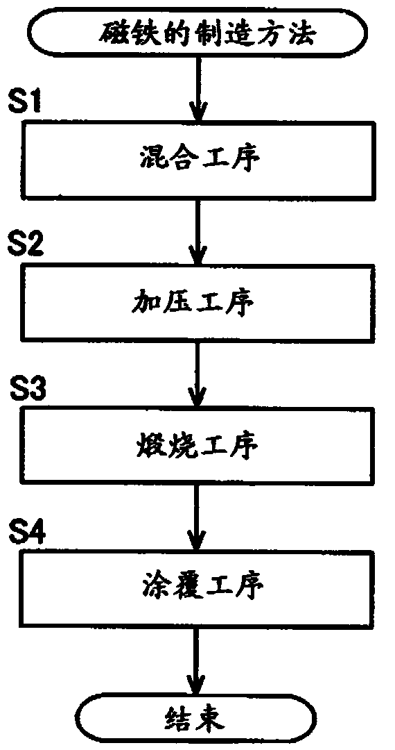
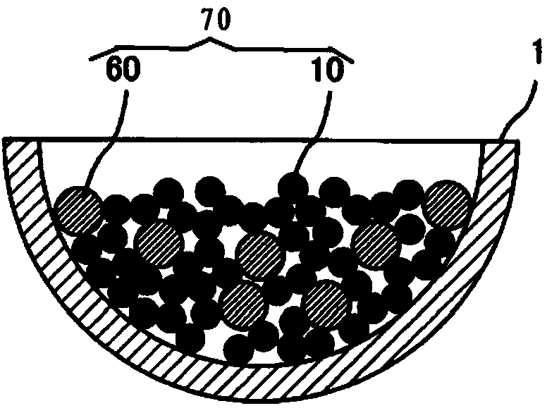
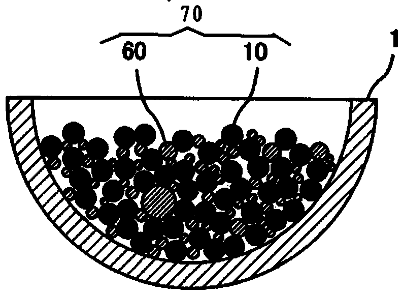
[0026] refer to Figure 1 to Figure 7 A magnet manufacturing method according to an embodiment of the present invention will be described. The magnetic powder 10 of hard magnetic body which is a raw material of a magnet, and the lubricant 60 which is powdery at normal temperature are prepared. Here, in this embodiment, binders such as resins that have been used conventionally are not used.

[0027] Then, if figure 1 and Figure 2A As shown, the prepared magnetic powder 10 and lubricant 60 are added to a mixing container 1 such as a mortar, and mixed to manufacture a mixed powder 70 ( figure 1 Step S1).

[0028] The magnetic powder 10 uses an R-Fe-N-based compound or an Fe-N-based compound containing a rare earth element as R. As the rare earth element R, rare earth elements other than dysprosium are preferable, light rare earth elements are particularly preferable, and among them, Sm is preferable. The light rare earth elements mentioned here are the elements whose atomi...


PUM

PropertyMeasurementUnit
particle sizeaaaaaaaaaa
densityaaaaaaaaaa

Abstract

There is provided a magnet manufacturing method with which a high residual magnetic flux density is obtained without using dysprosium (Dy) and without using a bonding agent. Magnetic powders (10) made of a hard magnetic material formed of a R-Fe-N compound containing a rare earth element as R or formed of a Fe-N compound are used. In a pressurizing step (S2), the magnetic powders (10) are pressurized by molds (2, 3) multiple times to form a primary compact (100). In a baking step (S3), a secondary compact (200) is formed by heating the primary compact (100) in an oxidizing atmosphere at a temperature lower than a decomposition temperature (Te2) of the magnetic powders (10) to bond together the outer surfaces of the adjacent magnetic powders (10) with oxide films formed on the outer surfaces of the magnetic powders (10).

Description

[0001] The disclosure of Japanese Patent Application No. 2013-132540 filed on June 25, 2013 and Japanese Patent Application No. 2013-132541 filed on June 25, 2013, including specification, drawings and abstract , incorporated herein by reference in its entirety. technical field [0002] The present invention relates to a method for manufacturing a magnet and a magnet. Background technique [0003] As an example of a conventional rare-earth magnet, JP-A-2007-39794 describes magnets containing Nd—Fe—B alloys and Sm—Fe—N alloys. Furthermore, this gazette describes a production method in which a soft magnetic metal is mixed with the above-mentioned alloy, followed by press molding and sintering. [0004] In addition, Japanese Patent Application Laid-Open No. 2012-69962 describes the following content: mix R-Fe-N-H magnetic material with soft magnetic powder, perform powder compaction, use shock waves in water to perform shock compression solidification, and shock-compressed Th...

Claims


Application Information

Patent Timeline
Patent Type & Authority Applications(China)
IPC IPC(8): H01F41/02B22F3/00
CPCH01F1/059H01F1/08H01F41/0266H01F1/10C01B21/0627C01B21/0622C01P2006/42
Inventor 三尾巧美西幸二马场纪行
Owner JTEKT CORP
Learn More