Method for producing rare earth magnet

A manufacturing method and technology of rare earth magnets, applied in the direction of inductance/transformer/magnet manufacturing, magnetic objects, magnetic materials, etc., can solve the problems that are not suitable for the manufacture of multi-variety or a small amount of magnet products, and achieve suppression of eddy current, crack suppression, The effect of increasing the residual magnetic flux density

Inactive Publication Date: 2019-06-21
TDK CORPARATION
View PDF17 Cites 0 Cited by
  • Summary
  • Abstract
  • Description
  • Claims
  • Application Information

AI Technical Summary

Problems solved by technology

[0005] Due to the reasons mentioned above, the existing manufacturing method utilizing the high-voltage magnetic field pressing method is not suitable for the manufacture of many varieties or a small amount of magnet products.

Method used


Image

  • Method for producing rare earth magnet
  • Method for producing rare earth magnet
  • Method for producing rare earth magnet

Examples


Embodiment 1

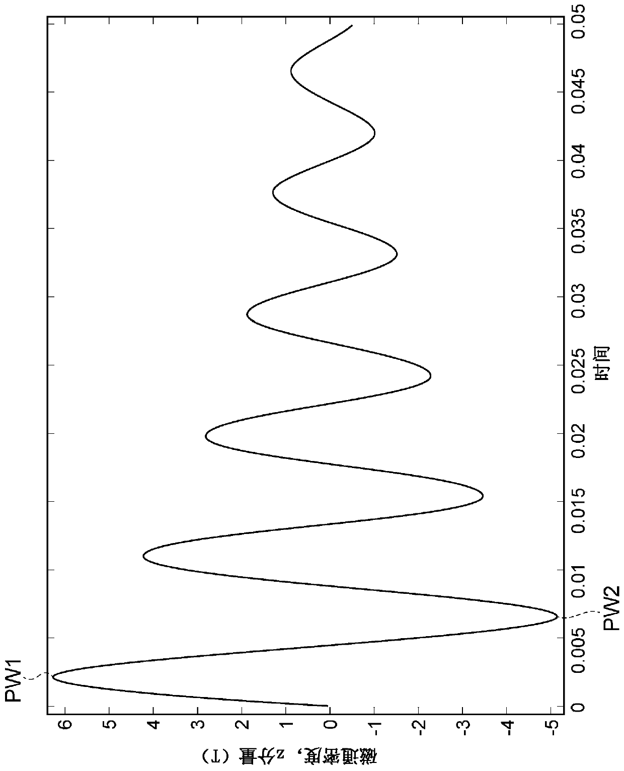
[0086] As described below, the orientation process of Example 1 was simulated by simulation using a computer. The simulation is based on the finite element method. As the simulation, COMSOL Multiphysics, which is a software manufactured by COMSOL Corporation, was used.

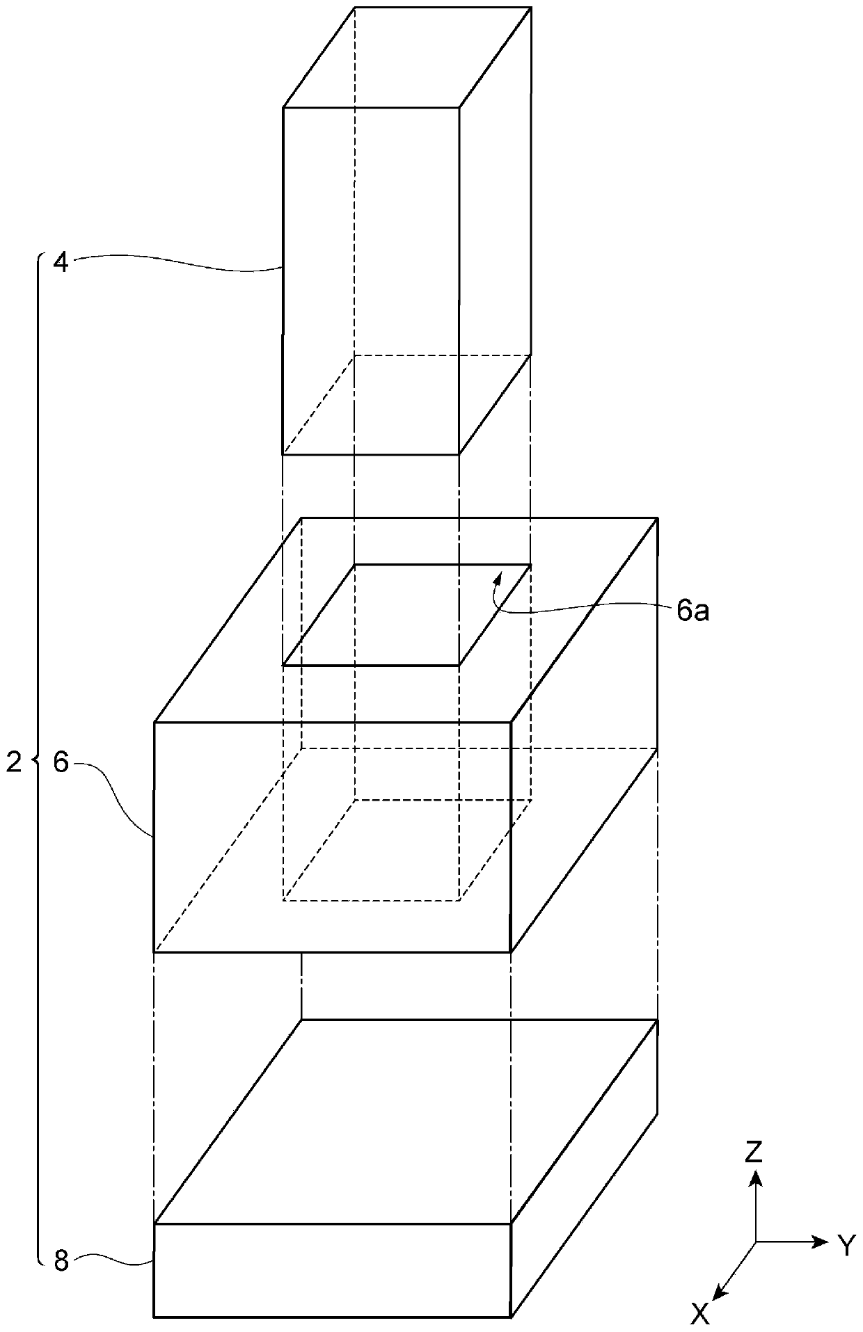
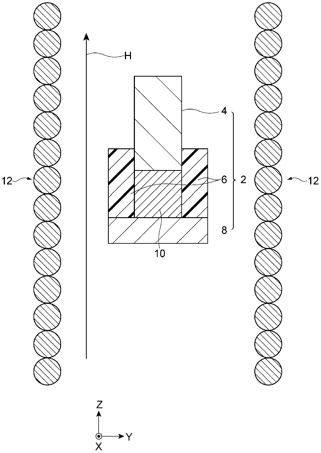
[0087] Such as Figure 4 As shown, in the orientation process of Example 1, a cylindrical side mold 6 made of acrylic resin was used. The side mold 6 and the cylindrical molded body 10 filled in the side mold 6 are arranged inside the hollow coil 12. Then, the pulse magnetic field H generated by the air-core coil 12 is applied to the side mold 6 and the molded body 10. The surface of the side mold 6 in contact with the molded body 10 (ie, the inner wall of the side mold 6) is parallel to the pulse magnetic field H. The side mold 6 and the molded body 10 are arranged at the center of the air-core coil 12 in the direction of the pulse magnetic field H. Inner diameter of side mold 6 (The diameter of the molded ...

Embodiment 2

[0154] Through thin strip continuous casting, the composition is Nd in weight fraction 29 Dy 1 Fe bal. B 1 The flaky alloy. The alloy is coarsely pulverized by the hydrogen adsorption method to obtain coarse powder. Add oleic acid amide (lubricant) to the coarse powder. Next, the coarse powder is pulverized in an inert gas by a jet mill to obtain a fine powder (metal powder containing rare earth elements). The particle size D50 of the fine powder was adjusted to 4 μm. The oxygen content in the fine powder is 5000 mass ppm or less. The nitrogen content in the fine powder is 500 mass ppm or less. The carbon content in the fine powder is 1000 mass ppm or less.

[0155] In the molding process, the fine powder to which oleic acid amide is added is fed into the mold to form a molded body. The details of the molding process are as follows.

[0156] The mold includes a rectangular lower mold, a rectangular parallelepiped side mold arranged on the lower mold, and an upper mold arran...

Embodiment 3~9、 and comparative example 2 and 3

[0168] In Examples 3 to 9 and Comparative Examples 2 and 3, the molding pressure was adjusted to the value shown in Table 2 below. In Examples 3-9 and Comparative Examples 2 and 3, the density of the molded body immediately after the molding process was adjusted to the value shown in Table 2 below by changing the quality of the fine powder supplied into the mold and the molding pressure . In each of Examples 3 to 9 and Comparative Examples 2 and 3, the density of the molded body immediately before the sintering process was substantially the same as the density of the molded body immediately after the molding process (density 1). Except for these matters, the same method as in Example 2 was used to produce molded bodies and rare earth magnets of Examples 3 to 9, and Comparative Examples 2 and 3, respectively.

[0169] In the same manner as in Example 2, the residual magnetic flux density Br of each of the rare earth magnets of Examples 3 to 9 and Comparative Examples 2 and 3 was ...


PUM

PropertyMeasurementUnit
particle diameteraaaaaaaaaa
strengthaaaaaaaaaa

Abstract

Provided is a method for producing a rare earth magnet, which suppresses eddy current in a mold when a metal powder containing a rare earth element is oriented within the mold, and which improves theresidual magnetic flux density of a rare earth magnet, while suppressing the occurrence of cracking in the rare earth magnet. This method for producing a rare earth magnet is characterized by comprising: a molding step wherein a metal powder containing a rare earth element is supplied into a mold 2 so as to form a molded body 10; an orientation step wherein a pulsed magnetic field H is applied tothe molded body 10 held in the mold 2 so as to orient the metal powder contained in the molded body 10; and a sintering step wherein the molded body 10 separated from the mold 2 is sintered after theorientation step. This method for producing a rare earth magnet is also characterized in that: at least a part of the mold 2 is formed from a resin; and the molded body is sintered after being adjusted to have a density of from 3.0 g / cm<3> to 4.4 g / cm<3> (inclusive).

Description

Technical field [0001] The invention relates to a method for manufacturing rare earth magnets. Background technique [0002] Rare earth magnets are components such as motors or actuators, and are used in hard disk drives, hybrid vehicles, electric vehicles, magnetic resonance imaging devices (MRI), smart phones, digital cameras, flat-screen TVs, scanners, air conditioners, heat pumps, Refrigerators, vacuum cleaners, washer dryers, elevators and wind generators and other fields. According to these various applications, the required size and shape of rare earth magnets are different. Therefore, in order to efficiently manufacture various types of rare earth magnets, a molding method that can easily change the size and shape of the rare earth magnets is desired. [0003] In the production of conventional rare earth magnets, a metal powder (for example, alloy powder) containing a rare earth element is pressurized under high pressure (for example, 50 MPa or more and 200 MPa or less), ...

Claims


Application Information

Patent Timeline
Patent Type & Authority Applications(China)
IPC IPC(8): H01F41/02B22F3/02C22C38/00H01F1/057
CPCC22C38/00B22F2998/10B22F2999/00B22F3/02B22F3/10H01F41/0273H01F1/0577B22F9/023B22F9/04B22F2202/05C22C2202/02B22F2009/044H01F1/0536H01F1/0557H01F1/059H01F41/0266
Inventor 铃木健一大畑修大泽明弘
Owner TDK CORPARATION
Why Eureka
Try Eureka