

Flexible capacitive micromachined ultrasonic transducer array with increased effective capacitance
A technology of capacitive micromachining and ultrasonic transducers, applied in piezoelectric devices/electrostrictive devices, circuits, electrical components, etc.
- Summary
- Abstract
- Description
- Claims
- Application Information
AI Technical Summary
Problems solved by technology
Method used
Image

Examples
Embodiment Construction
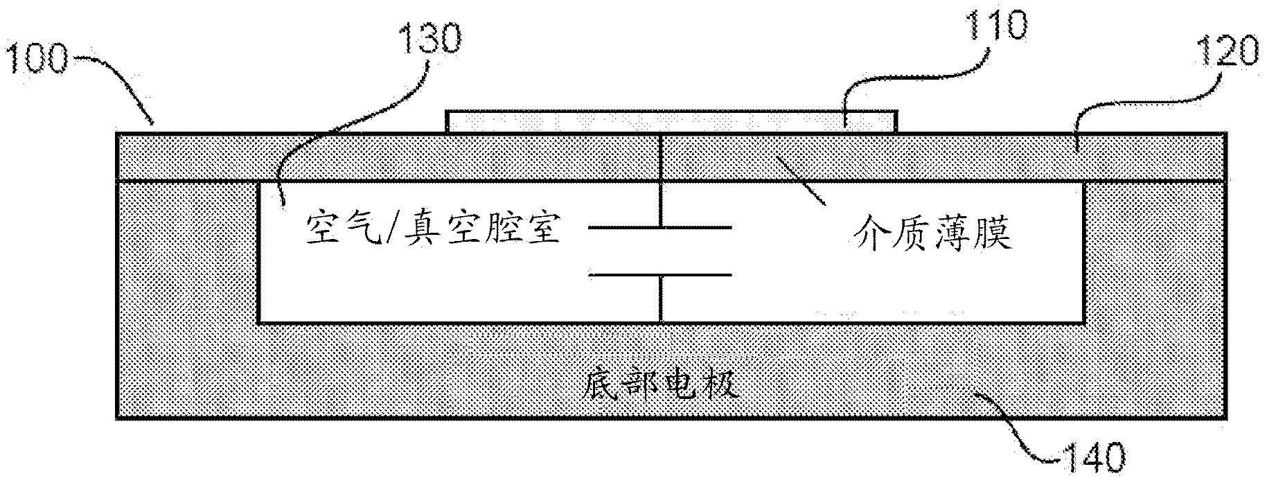
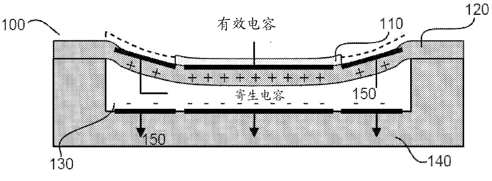
[0053] refer to Figures 8 to 10 , shows a capacitive micromachined ultrasound transducer (CMUT) 200 with a concave shaped bottom electrode 240 . The recessed air chamber 230 is defined by the recess of the bottom electrode 240 . go to Figure 8 , the top electrode 210 covers 100% of the area 260 of the membrane 220 above the air chamber 230 . Therefore, the effective capacitance of CMUT 200 can be significantly higher than figure 1 The effective capacitance of a conventional CMUT (which has a top electrode 110 covering only 25% of the membrane area 120) of .
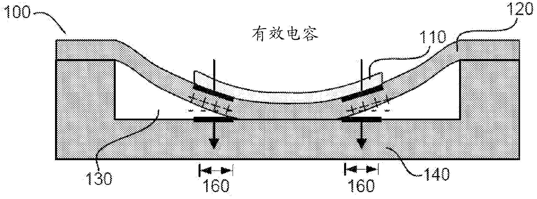
[0054] go to Figure 9 , the entire area 260 of the membrane 220 above the air chamber 230 is considered to develop an effective capacitance when a direct current (DC) bias is applied. The recess of the bottom electrode 240 substantially matches the deflection of the membrane 220 when a DC bias is applied.
[0055] If the bottom electrode 240 defines a concave shape or curved profile, the membrane 220 can fully f...
PUM
| Property | Measurement | Unit |
|---|---|---|
| Size | aaaaa | aaaaa |
| Thickness | aaaaa | aaaaa |
| Young's modulus | aaaaa | aaaaa |
Abstract
Description
Claims
Application Information