
Three-dimensional or four-dimensional automatic ultrasound image optimization and adjustment method

An ultrasound image, automatic optimization technology, applied in ultrasound/acoustic/infrasonic diagnosis, sonic diagnosis, infrasonic diagnosis, etc., can solve the problem of soft tissue image and non-soft tissue image definition without proper transition, unable to fully compensate for gain loss, soft tissue Image misjudgment and other problems, to achieve the effect of reducing diagnosis time, uniform brightness, and improving accuracy

Active Publication Date: 2012-06-20
CHISON MEDICAL TECH CO LTD
View PDF5 Cites 30 Cited by
  • Summary
  • Abstract
  • Description
  • Claims
  • Application Information

AI Technical Summary

Problems solved by technology

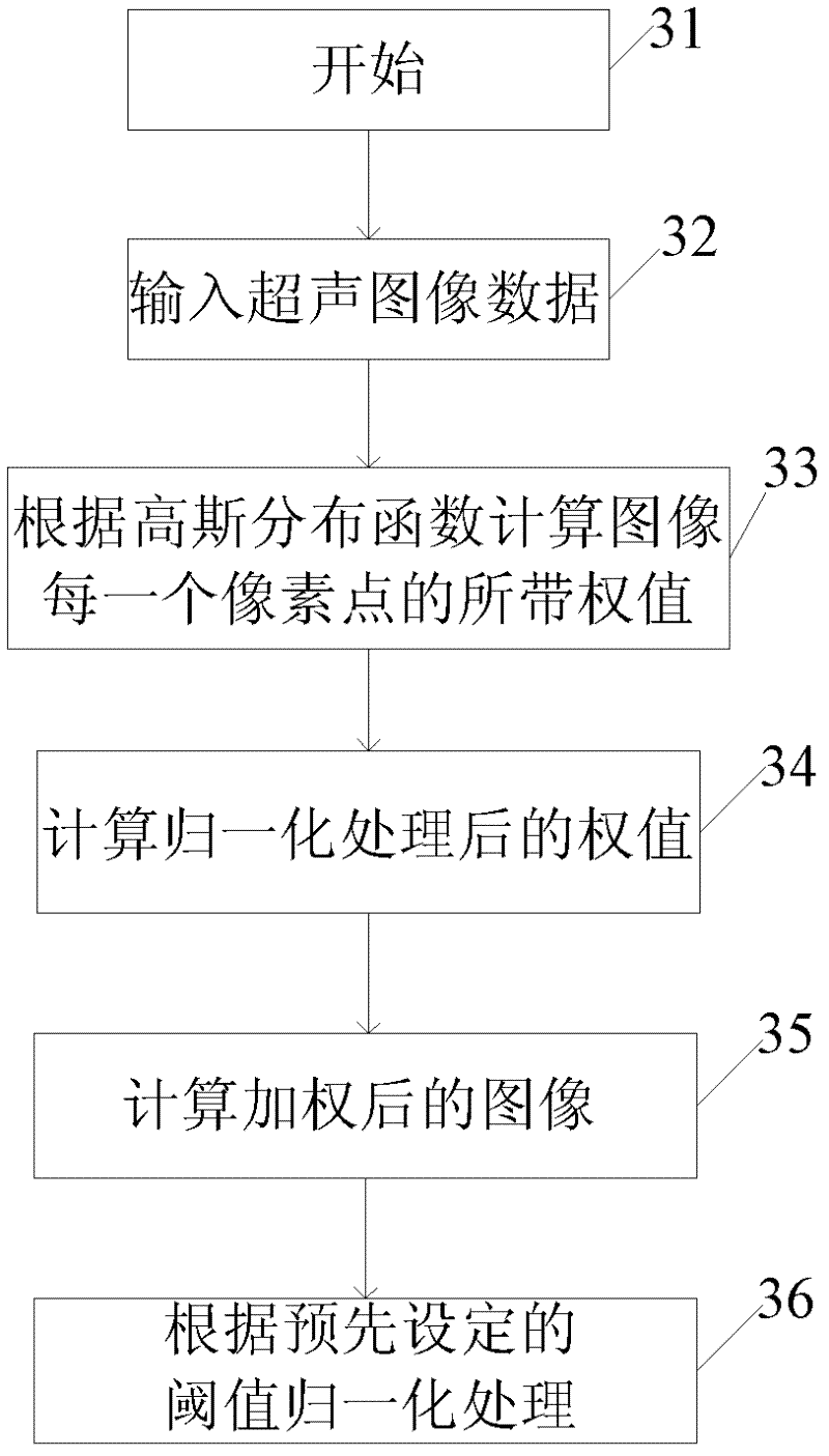
In this type of method, for the pixels in the sub-blocks after the image is divided into blocks, a preset threshold is often used to judge whether it is a pixel of a soft tissue image. If it is greater than the preset threshold, it is a pixel of a soft tissue image. It is marked with a value of 1, otherwise it is a pixel of a non-soft tissue image, and it is marked with a value of 0. The disadvantage of this is that after image segmentation, the values ​​corresponding to the pixels of the soft tissue image area are all 1, and the non-soft tissue image area (that is, the near field , noise in the far field, and cysts in soft tissue, etc.), the values ​​corresponding to the pixels are all 0, which makes the pixel values ​​of the entire image after segmentation discontinuous, and there is no proper transition for the definition between soft tissue images and non-soft tissue images , only relying on the value of 0 and 1 to distinguish, it is easy to make a wrong judgment on whether it is a soft tissue image
Although this method makes the brightness of the image more uniform not only in the depth direction, but also in the horizontal direction, since the brightness does not only show a weakening trend in the depth direction and the lateral direction, but may Non-uniform changes along any direction of the image, gain compensation only in two directions still cannot fully compensate for the gain loss caused by the increase of scanning time

Method used


Image

  • Three-dimensional or four-dimensional automatic ultrasound image optimization and adjustment method
  • Three-dimensional or four-dimensional automatic ultrasound image optimization and adjustment method
  • Three-dimensional or four-dimensional automatic ultrasound image optimization and adjustment method

Examples


Embodiment A

[0089] Considering that due to the attenuation of the echo signal, not only the brightness of each frame of ultrasound images along the depth direction and lateral direction is weakened, but also the brightness of the same position between two consecutive frames of images is also different with the increase of scanning time.

[0090] In order to better compensate the gain attenuation of the ultrasonic image along the depth direction D (depth), the lateral direction L (lateral) and the time direction T (time), the ultrasonic image (Dimagnormal) is recorded as I, and the following equation is established:

[0091] I=f(D i , L j ,T k )

[0092] Among them, D i , L j ,T k Represent the independent variables along the depth direction, lateral direction and time direction respectively, that is to say, the pixel value I(i, j, k) in the ultrasound image I is related to the three independent variables of image depth, lateral direction and scanning time function, which satisfies t...

Embodiment B

[0103] Current methods for real-time 3D imaging include but are not limited to using 2D phased array transducers, rocking linear array transducers, and rocking convex array transducers to generate 3D data, and can also be mechanically driven scanning or magnetic field spatial positioning Free arm scanning, etc. Taking the two-dimensional phased array transducer as an example, its crystal sheets are arranged in a matrix shape, and are evenly cut by vertical and horizontal multi-line fields to form multiple miniature square cells. When the probe emits sound velocity, it performs azimuth steering along the y-axis direction according to the phased array method to form a two-dimensional image, and then fan-shaped movement along the z-axis direction for stereo elevation steering to form a pyramid database. A series of discrete two-dimensional images collected Space positioning, and after pixel interpolation and smoothing of the gaps between adjacent slices, a three-dimensional datab...

Embodiment C

[0113] The above-mentioned embodiment A can automatically optimize and adjust the depth direction, horizontal direction and time direction, and in embodiment B can automatically optimize and adjust the depth direction, horizontal direction and longitudinal direction, but for the current four-dimensional color Doppler ultrasound only in three Adjustment in one direction cannot achieve sufficient optimization, because the four-dimensional ultrasound technology uses three-dimensional ultrasound images plus time dimension parameters, and continuously projects the stereoscopic images at different times in the three-dimensional ultrasound images according to the sequence of time periods , to form a real-time dynamic three-dimensional image, so it is obviously not sufficient to only consider the depth direction, lateral direction and longitudinal direction in embodiment B, and it is also necessary to consider the change of the pixel value of the ultrasonic image in the time dimension, ...


PUM


Abstract

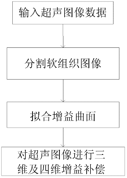
The invention discloses a three-dimensional and four-dimensional automatic ultrasound image optimization and adjustment method. The method comprises the following steps: inputting image data; dividing soft tissue image areas; fitting a gain plane; and carrying out three-dimensional and four-dimensional gain compensation on the images. The method has the following advantages: the weights carried by pixels of the envelop data before logarithmic compression or image data after logarithmic compression are computed according to the statistical parameters, or the soft tissue areas and the non-soft tissue areas are separated by utilizing the signal to noise ratio, then gain plane fitting is carried out on the areas, the gain compensation value is computed and the gain compensation value is used for carrying out three-dimensional and four-dimensional uniformity adjustment on the ultrasound images, thus ensuring the image brightness to be uniform and consistent.

Description

technical field [0001] The invention relates to an ultrasonic image gain optimization method, in particular to an automatic optimization and adjustment method for a three-dimensional or four-dimensional ultrasonic image. Background technique [0002] When ultrasound propagates in the human body, as the propagation distance deepens, the reflected ultrasound signal will decrease, making the ultrasound image appear uneven in brightness along the depth direction, which makes the soft tissue that plays an important role in the doctor's diagnosis often inaccessible. Displayed clearly and accurately. In order to obtain high-quality ultrasound images for doctors to diagnose, we need to take gain compensation measures so that the loss of image gain can be better compensated to achieve an ultrasound image with uniform brightness. [0003] The compensation for image gain in ultrasonic diagnostic equipment is generally for compensation in the depth direction, which is called DGC (Depth...

Claims


Application Information

Patent Timeline
Patent Type & Authority Applications(China)
IPC IPC(8): A61B8/00
Inventor 赵丹华许冠明赵明昌陆坚
Owner CHISON MEDICAL TECH CO LTD
Learn More