LED (light emitting diode) area light source module and method for obtaining uniform area light source white light

A technology of LED surface light source and surface light source, which is applied in the field of white light LED, and can solve problems such as complex device structure and complex process

Inactive Publication Date: 2012-06-20
SHANGHAI YAMING LIGHTING
View PDF11 Cites 7 Cited by
  • Summary
  • Abstract
  • Description
  • Claims
  • Application Information

AI Technical Summary

Problems solved by technology

Although this light-emitting device can obtain an ideal white light surface light source, the process of lens manufacturing and filling the light conversion material in the lens is complicated, and the structure of the device is correspondingly more complicated.

Method used


Image

  • LED (light emitting diode) area light source module and method for obtaining uniform area light source white light
  • LED (light emitting diode) area light source module and method for obtaining uniform area light source white light
  • LED (light emitting diode) area light source module and method for obtaining uniform area light source white light

Examples


Embodiment 1

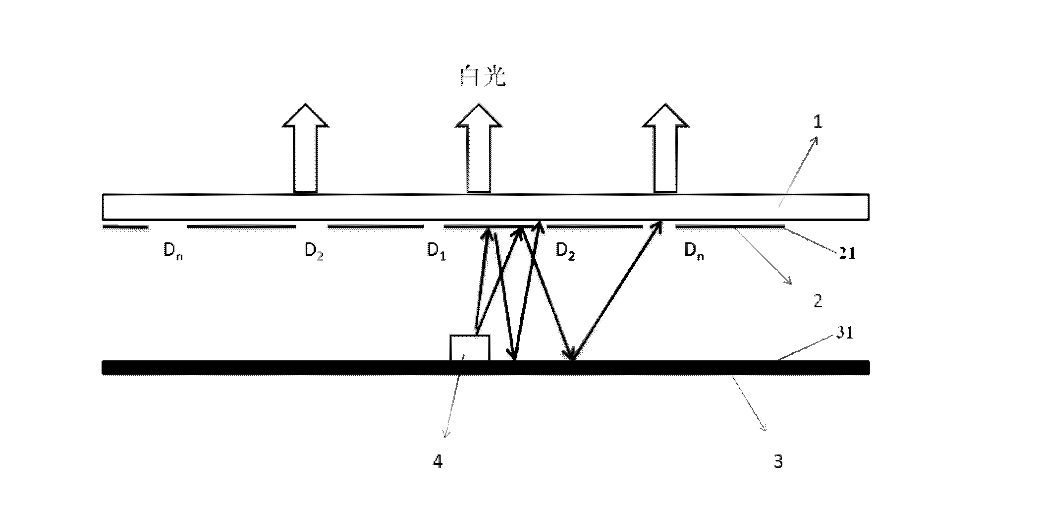
[0044] Example 1, figure 1 : (color temperature non-adjustable scheme)

[0045] Select a blue light device 4, place it in the center of the substrate 3, cover the mesh-shaped dodging plate 2, and cover the replaceable phosphor layer 1 on the dodging plate 2, which can form a uniform white light surface light source for the blue light point light source. The light emitted by the blue light device 4 is reflected from the first reflective surface 21 and the second reflective surface 31 or refracted and reflected multiple times by the first reflective surface 21 and the second reflective surface 31 from the holes (D1, D2) of the uniform light plate 2. ......Dn) emerges, first forming a uniform surface light source, and then entering the phosphor layer 1 to mix light. Specific as figure 1 shown. figure 1 middle, D 1 ...D n is the aperture distributed from the center to the periphery of the dodging plate. The main peak wavelength of the blue light device is 440-480nm, more pre...

Embodiment 2

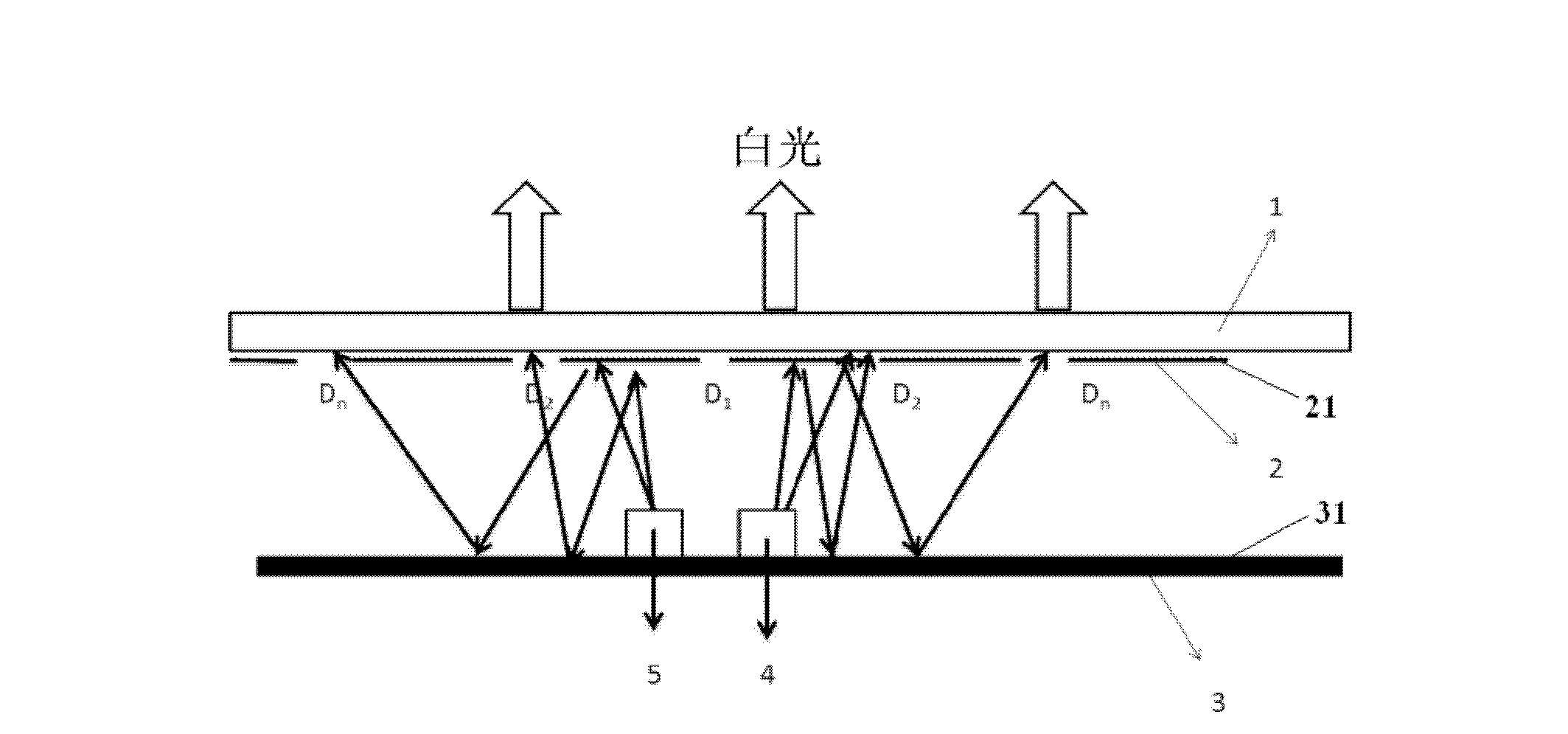
[0046] Example 2, figure 2 : (color temperature adjustable solution)

[0047] Select the blue light device 4 and the red light LED device 5, and place them in the center of the middle substrate 3 respectively, see figure 2 In the position shown, cover the mesh-shaped dodging plate 2, and cover the replaceable phosphor layer 1 on the dodging plate 2, which can form a uniform white light surface light source with a blue light point light source. The change of the color temperature is adjusted by adjusting the current of the red LED device. The light emitted by the blue light device 4 and the red light device 5 is reflected by the first reflective surface 21 and the second reflective surface 31 or refracted and reflected multiple times by the first reflective surface 21 and the second reflective surface 31 from each of the dodging plate 2. The holes ( D1 , D2 . . . Dn ) exit to form a uniform surface light source first, and then enter the phosphor layer 1 to mix light.

[00...


PUM


Abstract

The invention discloses an LED (light emitting diode) area light source module and a method for obtaining uniform area light source white light. The LED area light source module comprises a substrate; at least one LED point light source is arranged on the substrate; a light homogenizing plate is arranged above the LED point light source; a fluorescent powder layer is arranged above the light homogenizing plate; the lower surface of the light homogenizing plate is a first reflective surface; the upper surface of the substrate is a second reflective surface; a plurality of holes are arranged in the light homogenizing plate in an array manner; and the light emitted by the LED point light source is reflected by the first reflective surface and the second reflective surface many times, and enters into the fluorescent powder layer after being emergent through the holes in the light homogenizing plate. According to the LED area light source module disclosed by the invention, the emergent light optical path of the point light source is changed through the two reflective surfaces, and the light intensity is redistributed through the hole array on the light homogenizing plate, therefore a white-light area light source with uniform intensity is formed after the light passes through the LED area light source module. Compared with the traditional area light source formed by a plurality of point light sources, the number of the point light sources is reduced, and uniform light intensity distribution is realized.

Description

technical field [0001] The invention belongs to the technical field of white light LEDs, in particular to an LED surface light source module and a method for obtaining white light from a uniform surface light source. Background technique [0002] Since the LED white light lighting technology has gradually matured, LEDs have been widely used as various lighting sources. In the current LED lighting scheme, the application of LED as a new type of semiconductor lighting source in point light source can achieve a relatively uniform luminous intensity, but when the LED is used as a surface light source, there is a problem of uneven luminous intensity at each point, so that the overall luminous intensity has declined. The current solutions are as follows. Such as setting up multiple light sources, but multiple light sources occupy a certain space, and when the illuminated area is very close to the light source, the characteristics of the point light source are very prominent. Or...

Claims


Application Information

Patent Timeline
Patent Type & Authority Applications(China)
IPC IPC(8): F21S2/00F21V13/02F21Y101/02
Inventor 陈宇
Owner SHANGHAI YAMING LIGHTING
Why Eureka
Try Eureka