Water removal system of flow sensor

A flow sensor and solenoid valve technology, applied in the field of flow sensors, can solve the problems of flow sensor probe condensation, insufficient detection accuracy, and inaccurate detection of ventilators, etc., to prolong the use time and life, high detection accuracy, and reliable work Effect

Inactive Publication Date: 2012-06-20
于邦仲
View PDF6 Cites 0 Cited by
  • Summary
  • Abstract
  • Description
  • Claims
  • Application Information

AI Technical Summary

Problems solved by technology

In medical electronic equipment, such as a ventilator, it is necessary to detect the user's breathing flow. The main channel inlet / outlet of the flow sensor probe FQ2 is close to the user. Since the patient exhales hot and humid gas, it condenses after meeting the tube wall, making Condensation inside the flow sensor probe FQ2, especially the detection of condensation in the airway 11, causes inaccurate detection of the ventilator and insufficient detection accuracy, thus affecting the precise control of the ventilator

Method used


Image

  • Water removal system of flow sensor
  • Water removal system of flow sensor
  • Water removal system of flow sensor

Examples


Embodiment Construction

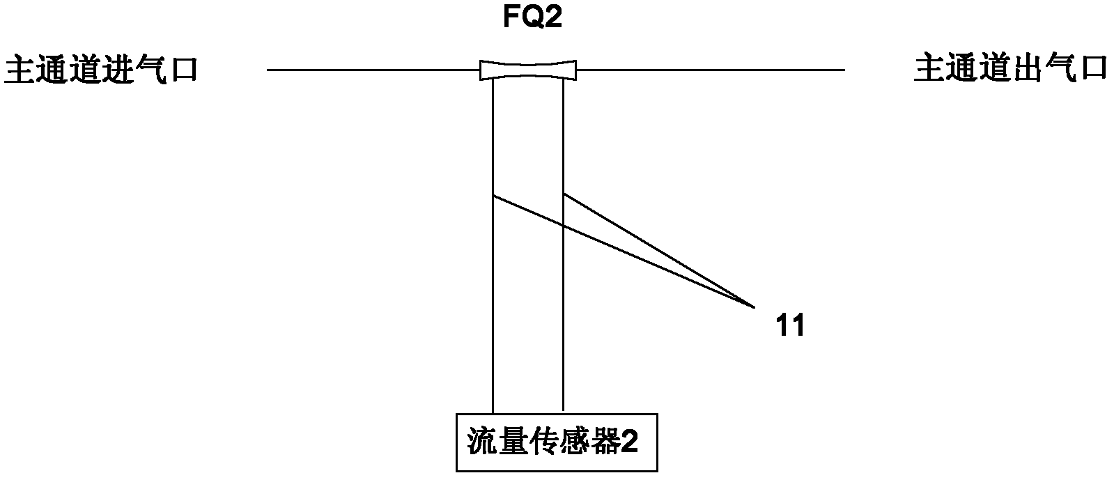
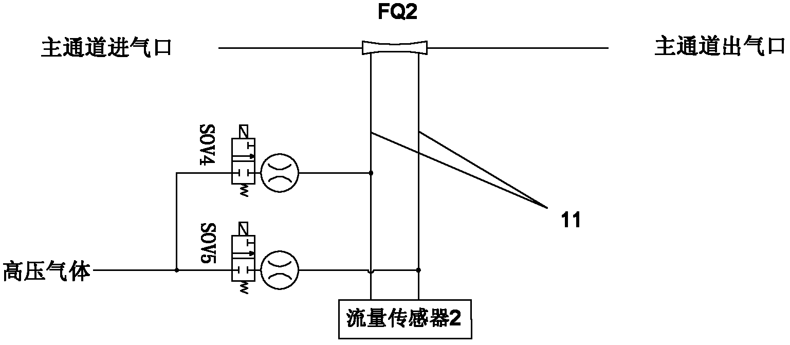
[0025] According to the first embodiment of the present invention, the flow sensor water removal system has a gas path structure such as figure 2 As shown, the gas path is connected to the flow sensor 2 and the flow sensor probe FQ2, and includes a first solenoid valve SOV4 and a second solenoid valve SOV5 respectively arranged on the bypass cross pipe of the respective linear detection branch gas path 11, and the outside is connected to high-pressure gas , This high-pressure gas can be the output gas of a decompressed oxygen cylinder.

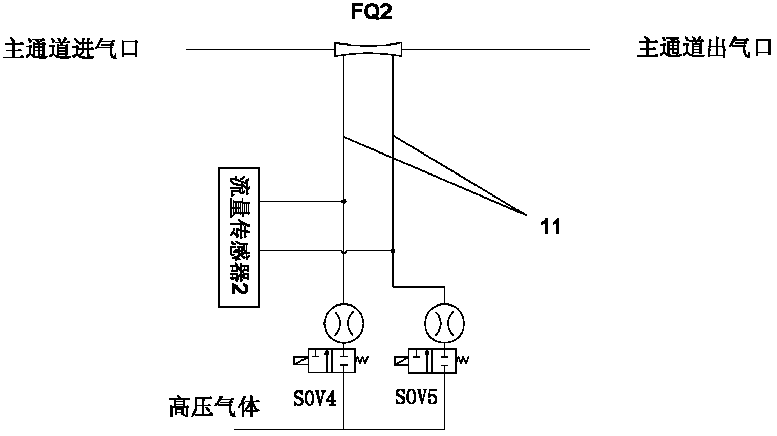
[0026] The water removal system of the flow sensor of the second embodiment of the present invention has a gas path structure such as image 3 As shown, the gas path communicates with the flow sensor 2 and the flow sensor probe FQ2, and includes a first solenoid valve SOV4 and a second solenoid valve SOV4 and a second solenoid valve SOV4 and a second solenoid valve respectively arranged on a conducting pipe which is in a straight line with one si...


PUM


Abstract

The invention relates to a water removal system of a flow sensor; an air channel is communicated with a flow sensor(2) and a flow sensor probe (FQ2), the water removal system of the flow sensor comprises a first electromagnetic valve (SOV4) and a second electromagnetic valve (SOV5), and a control unit, wherein bypass air channels at one ends of the first electromagnetic valve and the second electromagnetic valve are communicated with a corresponding detection branch air channel (11) between the flow sensor and the flow sensor probe (FQ2), an air channel at the other ends of the first electromagnetic valve and the second electromagnetic valve is connected with high-pressure air; the control unit which is electrically connected with control ends of the first electromagnetic valve and the second electromagnetic valve and is used for controlling the first electromagnetic valve and the second electromagnetic valve to be closed for performing the flow detection or controlling the first electromagnetic valve and the second electromagnetic valve to be opened for performing water removal or dredging by utilizing the high-pressure air. The water removal system of the flow sensor can be used for removing the condensed water in the detection branch air channel, and the flow sensor is accurate in detection, is reliable in usage and is long in service life.

Description

Technical field [0001] The invention relates to a flow sensor, in particular to a water removal system for a flow sensor, and is especially used in medical electronics. Background technique [0002] Such as figure 1 As shown, the flow sensor probe FQ2 is connected in series on the main gas path, and is connected to the flow sensor 2 through two detection branch gas paths 11, thereby detecting the gas flow of the main path gas path and providing it to the circuit control unit or part. In medical electronic equipment, such as ventilators, it is necessary to detect the user’s breathing flow. The air inlet / outlet of the main channel of the flow sensor probe FQ2 is close to the user. Because the patient exhales hot and humid gas, it condenses when it meets the tube wall. The internal condensate of the flow sensor probe FQ2, especially the condensed water in the branch air circuit 11, causes the ventilator to detect inaccurately, and the detection accuracy is insufficient, which affect...

Claims


Application Information

Patent Timeline
Patent Type & Authority Applications(China)
IPC IPC(8): G01F15/00G01F1/34
Inventor 李翠萍陈炜静顾志超
Owner 于邦仲
Why Eureka
Try Eureka