Ultrasonic time-of-flight diffraction method by cylinder focusing wedge

A diffraction time difference method and wedge block technology, which is applied to the analysis of solids using sonic/ultrasonic/infrasonic waves, can solve problems such as the need to improve the detection sensitivity and the low energy level of the diffraction signal, and achieve the effect of improving the identification ability and avoiding the missed detection of defects.

Inactive Publication Date: 2012-06-20
HARBIN INST OF TECH
3 Cites 7 Cited by

AI-Extracted Technical Summary

Problems solved by technology

[0004] The purpose of the present invention is to solve the problem that the existing diffraction time-of-flight method detects defects, the energy level of the diffra...

Abstract

An ultrasonic time-of-flight diffraction method by a cylinder focusing wedge relates to the field of ultrasonic detection and solves the problem that an existing time-of-flight diffraction method for detection is low in energy level of defective diffraction signals and needs improvement of detecting sensitivity. The ultrasonic time-of-flight diffraction method includes the specific steps: firstly, determining known conditions including the diameter of a probe wafer, the longitudinal wave velocity of the wedge, the longitudinal wave velocity of a detected workpiece and the velocity of longitudinal waves in water; secondly, setting needed conditions including the water path of an acoustic beam of a spindle, the refraction angle of longitudinal waves in the detected workpiece and the focusing vertical depth of the acoustic beam of the spindle in the workpiece; and thirdly, computing the curvature radius of a cylinder of the wedge according to the conditions and detecting by the ultrasonic time-of-flight diffraction method through the manufactured cylinder focusing wedge. The ultrasonic time-of-flight diffraction method is used for ultrasonic detection.

Application Domain

Technology Topic

Refraction angleEnergy level +5

Image

  • Ultrasonic time-of-flight diffraction method by cylinder focusing wedge
  • Ultrasonic time-of-flight diffraction method by cylinder focusing wedge
  • Ultrasonic time-of-flight diffraction method by cylinder focusing wedge

Examples

  • Experimental program(2)

Example Embodiment

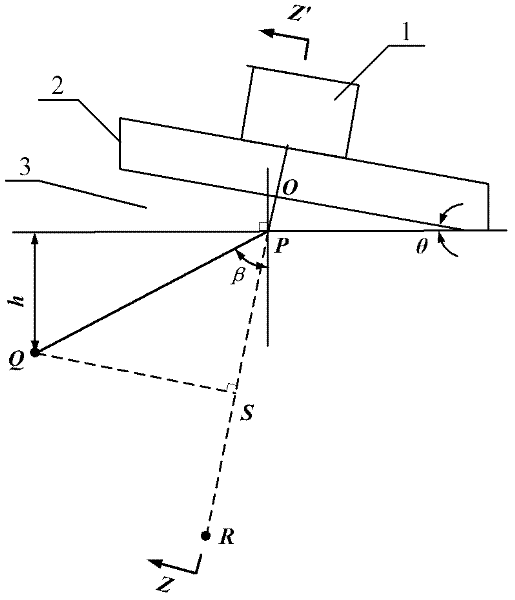
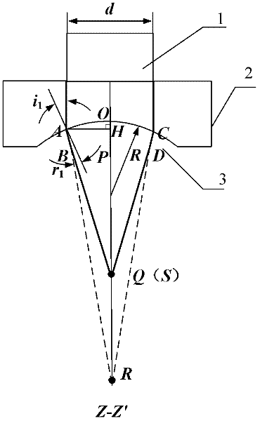
[0042] Specific implementation mode 1: Combination figure 1 with figure 2 To describe this embodiment, the specific steps included in this embodiment are as follows:
[0043] Step 1. Determine the known conditions: the diameter of the probe wafer, the longitudinal wave speed of the wedge, the longitudinal wave sound speed of the tested workpiece, and the longitudinal wave sound speed in water;
[0044] Step 2. Set the required conditions: the water path of the spindle sound beam, the refraction angle of the longitudinal wave in the tested workpiece, and the vertical depth of focus of the spindle sound beam in the workpiece;
[0045] Step 3: Calculate the radius of curvature of the wedge cylinder according to the above conditions:
[0046] The incident angle of the sound beam emitted by the probe on the curved surface is i 1 , The refraction angle after curved surface refraction is r 1 , Stipulating the refraction angle β of the sound beam at the interface between the water and the tested plate, the incident angle is equal to the wedge inclination angle θ, then according to the law of refraction:
[0047] sinθ/sinβ=v water /v Sheet (1)
[0048] Solve formula (1) to get the angle of θ;
[0049] Suppose the main shaft sound beam passes through the wedge and the water coupling layer and focuses on the thickness depth h of the tested object:
[0050] PQ = h / cos β PS = PQ X cos ( β - θ ) - - - ( 2 )
[0051] Solve formula (2) to get the focal length PS length in the tested plate;
[0052] According to the principle of geometric optics, PS and PR have the following relationship:
[0053] PS/PR=v water /v Sheet (3)
[0054] Solve formula (3) to get the PR length of the focal length in water;
[0055] According to the law of refraction and geometric relations,
[0056]
[0057] Solution (4) i 1 angle;
[0058] sini 1 =(d/2)/R (5)
[0059] Solve formula (5) to get the radius of curvature of the wedge R;
[0060] Among them, the formulas (4) and (5) are solved as follows:
[0061] Suppose
[0062] (d/2)/(OP+PR)=a
[0063] i 1 -r 1 =c (6)
[0064] v water /v aluminum = B
[0065] Then there is
[0066] sin(i 1 -r 1 )=a
[0067] i 1 -r 1 =c (7)
[0068] sin i 1 sin r 1 = b
[0069] And have the following derivation
[0070] sin ( r 1 + c ) sin r 1 = b
[0071] ⇒ sin r 1 cos c + cos r 1 sin c sin r 1 = b
[0072] ⇒ cos c + 1 tan r 1 sin c = b - - - ( 8 )
[0073] ⇒ tan r 1 = b - cos c sin c
[0074] ⇒ r 1 = tan - 1 ( b - cos c sin c )
[0075] ⇒ i 1 = r 1 + c = tan - 1 ( b - cos c sin c ) + c
[0076] Solve for i 1 , Use the manufactured cylindrical focusing wedge to implement the ultrasonic diffraction time difference detection.

Example Embodiment

[0077] Specific embodiment 2: This embodiment adopts the technical scheme of specific embodiment 1, and experiments are carried out in combination with a specific environment to illustrate the effect of the present invention. The aluminum alloy plate with a thickness of 10.5 mm is used as the detection object, and the wedge is made of organic glass:
[0078] Step 1. Determine the known conditions: probe wafer diameter d=6mm, plexiglass longitudinal wave sound velocity v Plexiglass =2730m/s, the longitudinal wave sound velocity of the tested workpiece v aluminum =6260m/s, longitudinal wave sound velocity in water v water =1480m/s;
[0079] Step two, set the required conditions: the spindle sound beam water path OP=1.5mm, the longitudinal wave refraction angle θ=60° in the inspected workpiece, and the focal depth of the spindle sound beam in the workpiece h=5.3mm;
[0080] Step 3: Calculate the radius of curvature of the wedge:
[0081] The incident angle of the sound beam emitted by the probe on the curved surface is i 1 , The refraction angle after curved surface refraction is r 1. It is stipulated that the refraction angle of sound beam at the interface between water and aluminum alloy plate is β=60°. The incident angle is equal to the inclination angle θ of the wedge, according to the law of refraction,
[0082] sinθ/sinβ=v water /v aluminum (1)
[0083] Solving formula (1), θ=11.6°.
[0084] Suppose the main shaft sound beam passes through the wedge and the water coupling layer, and then focuses on 1/2 of the thickness of the subject, that is, the depth h is 5.3mm.
[0085] PQ = h / cos β PS = PQ X cos ( β - θ ) - - - ( 2 )
[0086] Solving formula (2), PS=7.0mm.
[0087] According to the principle of geometric optics, PS and PR have the following relationship:
[0088] PS/PR=v water /v aluminum (3)
[0089] Solving formula (3), PR = 30.2mm.
[0090] According to the law of refraction and geometric relations,
[0091]
[0092] Solving formula (4), i 1 = 11.8°.
[0093] sini 1 =(d/2)/R (5)
[0094] Solving formula (5), the wedge radius of curvature R is 11.63mm.
[0095] In step three, the solutions of formulas (4) and (5) are as follows:
[0096] Suppose
[0097] (d/2)/(OP+PR)=a
[0098] i 1 -r 1 =c (6)
[0099] v water /v aluminum = B
[0100] Then there is
[0101] sin(i 1 -r 1 )=a
[0102] i 1 -r 1 =c (7)
[0103] sin i 1 sin r 1 = b
[0104] And have the following derivation
[0105] sin ( r 1 + c ) sin r 1 = b
[0106] ⇒ sin r 1 cos c + cos r 1 sin c sin r 1 = b
[0107] ⇒ cos c + 1 tan r 1 sin c = b - - - ( 8 )
[0108] ⇒ tan r 1 = b - cos c sin c
[0109] ⇒ r 1 = tan - 1 ( b - cos c sin c )
[0110] ⇒ i 1 = r 1 + c = tan - 1 ( b - cos c sin c ) + c
[0111] From this, i can be solved 1.
[0112] The effect of the invention: the wedge produced by processing such as image 3 Shown. Processing flat-bottomed holes of different depths on a high-strength aluminum alloy plate with a thickness of 10.5mm as artificial defects. The artificial defect specimens and their detection methods are as follows Figure 4 Shown. See the buried depth of each artificial defect Figure 5. Choose a pair of broadband narrow pulse probe (chip size Center frequency 5MHz), using water as couplant to detect artificial defect test blocks. At the probe pitch of 23mm, the flat-bottomed holes were scanned by the conventional time-difference method and the cylindrical focus diffraction time-lapse method. When the detected lateral wave amplitudes account for 40% of the full screen, the D-scan image detected by the conventional method is as Image 6 As shown, the D-scan image detected by the focus method is as follows Figure 7 Shown. It can be seen that the contrast of the defect image detected by the focusing method in the background image has been greatly improved, making it easier to identify. So as to improve the detection sensitivity of the system without increasing the pulse emission energy.

PUM

PropertyMeasurementUnit
Thickness10.5mm
tensileMPa
Particle sizePa
strength10

Description & Claims & Application Information

We can also present the details of the Description, Claims and Application information to help users get a comprehensive understanding of the technical details of the patent, such as background art, summary of invention, brief description of drawings, description of embodiments, and other original content. On the other hand, users can also determine the specific scope of protection of the technology through the list of claims; as well as understand the changes in the life cycle of the technology with the presentation of the patent timeline. Login to view more.

Similar technology patents

Variable step size sparse augmented complex adaptive filter

PendingCN111884625AImprove identificationFast convergenceAdaptive networkElectronic communicationLeast mean squares filter
Owner:SUZHOU UNIV

Classification and recommendation of technical efficacy words

  • Improve identification
  • Avoid missing defects

Tape cartridge format identification in a single reel tape handling device

InactiveUS6918554B2Improve identificationReduce damagePicture changing apparatusAccessories for auxillary signalsEngineeringMagnetic tape
Owner:QUANTUM CORP

Method and device for reorganizing electronic file information

ActiveCN104361018AImprove identificationReduce duplication of effortSemi-structured data mapping/conversionSpecial data processing applicationsElectronic documentDigital document
Owner:李名选 +4
Why Eureka
Try Eureka