On-off automatic detection device for loops of collector ring

An automatic detection device and technology of confluence rings, which are applied in the field of devices for automatically detecting the on-off status of confluence rings, and detection devices for detecting circuit on-off in electromechanical devices, can solve problems such as inconvenient recording, test errors, and complicated operations. To achieve the effect of short detection time, reliable detection results and avoiding test errors

Active Publication Date: 2012-06-20
CHINA NORTH IND NO 205 RES INST
View PDF5 Cites 9 Cited by
  • Summary
  • Abstract
  • Description
  • Claims
  • Application Information

AI Technical Summary

Problems solved by technology

This test method is complicated to operate and inconvenient to record, especially for the confluence ring with a large number of loops, it will increase the fatigue of the testers and cause test errors
The current bus ring automatic detection device is only used to detect the contact resistance, insulation resistance, dielectric strength and phase characteristics of the bus ring loop. It does not test the loop continuity of the bus ring, and cannot intuitively see whether the loop exists. Problems with short circuit or open circuit

Method used


Image

  • On-off automatic detection device for loops of collector ring
  • On-off automatic detection device for loops of collector ring
  • On-off automatic detection device for loops of collector ring

Examples


Embodiment Construction

[0009] The present invention will be further described in detail below in conjunction with the accompanying drawings and preferred embodiments.

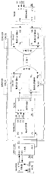
[0010] Such as figure 1 As shown, the slip ring automatic detection device in this embodiment is used for detection of slip rings with 64 loops. The detection device consists of 1 single-chip microcomputer of model C8051F320, 1 address latch of model 74VHC373, 2 decoders of model 74138, 2 CPLDs of model EPM7128, and a level shifter of model MAX232 It is composed of a control computer with a display.

[0011] The P0 mouth of the one-chip computer is connected with the input port D0-D7 of the address data latch, the data input port D0-D7 of CPLD1 and the data output port O0-O7 of CPLD2. CPLD1 contains data latch N n And n=1, 2, 3..., N, CPLD2 contains data latch K k , k=1, 2, 3..., K. Data Latch N n With output pin M nm And m=1, 2, 3..., M, the data latch K k With input pin J kj And j=1, 2, 3 . . . , J. In this preferred embo...


PUM


Abstract

The invention discloses an on-off automatic detection device for loops of a collector ring and belongs to the field of electric performance testing of an electromechanical device. The device is respectively connected with a loop lead and an electric brush lead of the detected collector ring through two complex programmable logic devices CPLD to establish a plurality of measuring loops and is used for realizing a man-machine operation interface by operating and controlling a computer; a used singlechip is used for realizing locking and gating of each measuring loop by an address latch and two decoders; and the singlechip is used for sequentially sending high-level data to an output pin at an initial end, i.e. the CPLD 1, of each measuring loop by built-in software and reading the level data transmitted back through the collector ring on all input pins at a tail end, i.e. the CPLD 2, of each measuring loop each time when sending one piece of high-level data so as to judge the state of the loops of the collector ring, i.e. switching-on or switching-off or shirt circuit. The device solves the problem of automatically detecting the on-off states of a plurality of loops of the collector ring. The on-off automatic detection device for the loops of the collector ring has high detection efficiency, is convenient to operate, is visual to display and has higher superiority for the collector ring with a large number of the loops.

Description

technical field [0001] The invention belongs to the field of electrical performance measurement of electromechanical devices, and relates to a detection device for detecting the on-off state of a circuit in an electro-mechanical device, in particular to a device capable of automatically detecting the on-off state of a confluence ring. Background technique [0002] The slip ring is an electromechanical device that transmits power and information between mechanisms with relative rotational motion. Its characteristic is that there can be multiple current channels on one circumference, and there will be no cable twisting due to the 360° rotation of the rotor fixed with it. Slip rings have been widely used now, especially in weapon systems such as airborne photoelectric stabilization, artillery control systems, and rotating radar antennas. According to different product requirements, the number of wires installed in the bus ring is also different. The bus ring used for airborne ...

Claims


Application Information

Patent Timeline
Patent Type & Authority Applications(China)
IPC IPC(8): G01R31/02
Inventor 霍丽烨庞澜吕勃龙宁飞蒋萧村
Owner CHINA NORTH IND NO 205 RES INST
Why Eureka
Try Eureka