Method for distinguishing fault type and direction of AT (auto-transformer) contact network without depending on GPS (global positioning system) time synchronization

A fault type and direction identification technology, applied in the fault location, measuring device, instrument and other directions, can solve the problem of affecting the location of the fault point, unable to judge whether the fault direction is upstream or downstream, not installing current transformers, etc., to ensure data. Synchronization, shorten troubleshooting time, and restore power in time

Active Publication Date: 2012-06-20
南京国电南自轨道交通工程有限公司
View PDF4 Cites 33 Cited by
  • Summary
  • Abstract
  • Description
  • Claims
  • Application Information

AI Technical Summary

Problems solved by technology

[0004]Question 1. The principle of suction current ratio is to measure the fault point by using the magnitude of the suction current of the AT autotransformers on both sides of the fault point. The suction current on both sides of the point must be the value at the same moment after the fault, and the data synchronization of each distance measuring device depends on GPS time synchronization.
Regardless of whether a built-in GPS plug-in or an external GPS timing system is used, when the GPS antenna is abnormal, it will inevitably affect the location of the fault point
[0005]Question 2. Since the parameters such as the impedance of the upstream and downstream catenary lines are the same under the AT power supply mode, when a fault occurs, the contact line of the upstream line collected by the substation is (T-line) current IT1 and forward feeder (F-line) current IF1 are equa

Method used


Image

  • Method for distinguishing fault type and direction of AT (auto-transformer) contact network without depending on GPS (global positioning system) time synchronization
  • Method for distinguishing fault type and direction of AT (auto-transformer) contact network without depending on GPS (global positioning system) time synchronization
  • Method for distinguishing fault type and direction of AT (auto-transformer) contact network without depending on GPS (global positioning system) time synchronization

Examples


Embodiment Construction

[0014] The present invention will be described in further detail below in conjunction with the accompanying drawings and specific embodiments. The drawings and specific embodiments do not limit the scope of protection claimed by the present invention.

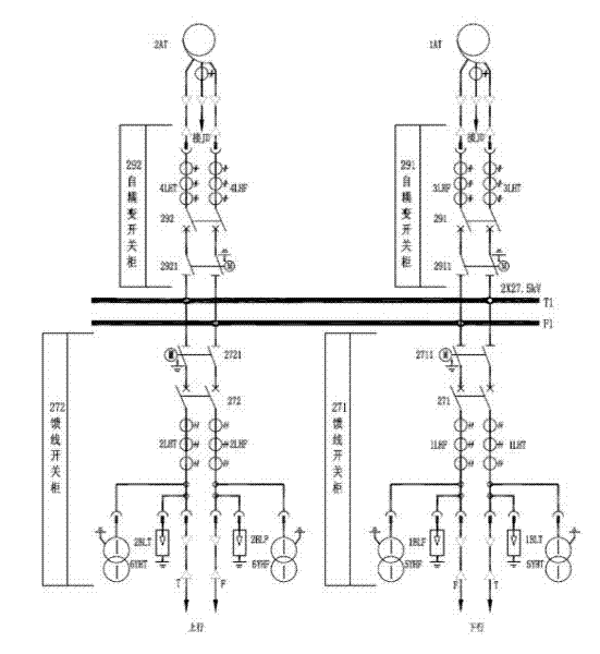
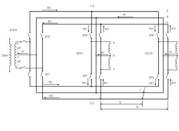
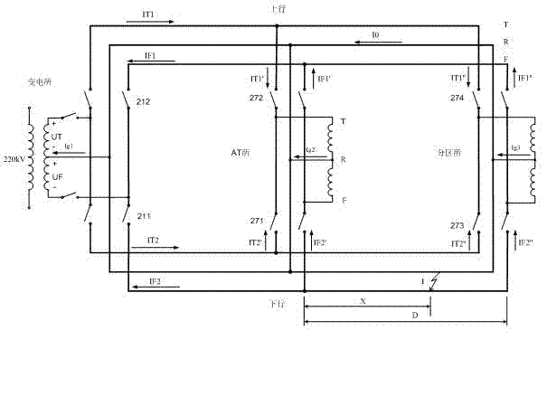
[0015] The principle of the suction current ratio is to use the suction current of the AT autotransformer on both sides of the fault point to measure the fault point. The suction current on both sides of the fault point must be the value at the same time after the fault. When a short-circuit fault occurs on the line, no matter where the short-circuit point is, the voltages of the T-line and F-line of the substation, AT station, and divisional station will suddenly drop from 27.5KV. The inventor uses this feature to ensure that each distance measurement on the line Synchronization of fault time data collected by the device. The specific implementation method is: the fixed value of the voltage mutation can be set on each device....


PUM


Abstract

The invention discloses a method for distinguishing the fault type and direction of a high-speed electrified railway AT (auto-transformer) contact network. The method can ensure the data synchronization of each ranging device on the same power supply arm without depending on the GPS (global positioning system) time synchronization and can judge the fault type and direction based on effective values of T-line and F-line current values without calculating current angles. The distinguishing method is simple and practical, can make accurate judgment on the fault type and the fault direction to enable the conditions of fault points to be more detailed, can effectively shorten the fault removal time for railway power supply maintenance department and is essential to restore power supply in real time. The method provided by the invention is bound to create favorable economic benefit under the background of increasing high-speed rail mileage.

Description

technical field [0001] The invention belongs to the field of AT traction power supply systems for high-speed electrified railways. The invention relates to the discrimination of various short-circuit types and directions of catenary faults of electrified railways using a parallel autotransformer (AT) power supply mode. Background technique [0002] As an important part of the high-speed electrified railway traction power supply system, the electrified railway catenary of AT power supply mode plays a decisive role in the safe and stable operation of railway transportation power supply. Due to the use of pantograph sliding to take current, the catenary failure probability is very high. Catenary line faults can be roughly divided into two types: transient faults and permanent faults. Instantaneous faults can be restored by reclosing the power supply, but the fault point is often a weak point, which needs to be found and dealt with as soon as possible, so as to prevent another...

Claims


Application Information

Patent Timeline
IPC IPC(8): G01R31/02G01R31/08
Inventor 王丹孙金华刘伟
Owner 南京国电南自轨道交通工程有限公司
Why Eureka
Try Eureka