
Cutter edge modification method for processing helicoid of screw rotor

A helical surface and rotor technology, which is applied in the design and correction of the cutter blade shape, can solve the problems that the rotor cannot mesh normally, the application occasions are few, and the energy consumption of the compressor is increased.

Active Publication Date: 2012-06-20
NORTHWESTERN POLYTECHNICAL UNIV
View PDF3 Cites 8 Cited by
  • Summary
  • Abstract
  • Description
  • Claims
  • Application Information

AI Technical Summary

Problems solved by technology

[0003] In practical applications, due to factors such as unavoidable manufacturing and installation errors, deformation during operation, and wear of parts, it is necessary to leave a certain gap between the actual machined rotor tooth surface and the theoretical tooth surface when machining the rotor. Therefore, it is often necessary to correct the tool edge shape obtained by theoretical calculation. At present, the commonly used correction method in China is to increase the center distance or deep cut during the processing. This method itself is relatively simple and easy to implement, but due to the processed The clearance between the theoretical rotor end face and the actual rotor end face varies from place to place, and the normal clearance between the theoretical rotor tooth surface and the actual rotor tooth surface also varies from place to place, so this method is not suitable for occasions
Another commonly used method is the equidistant profile method and the equidistant tool edge method. Although these two methods reduce the magnitude of the normal clearance change to varying degrees compared with the method of increasing the center distance or the deep cutting method, they still exist. The case where the tooth valley clearance is the largest and the tooth side clearance is small, in this case, the rotor is easily stuck during the meshing movement, or the compressed gas leaks to varying degrees, resulting in the abnormal meshing movement of the rotor and shortening the life of the compressor Or reduce the compression ratio and volumetric efficiency to increase the energy consumption of the compressor

Method used

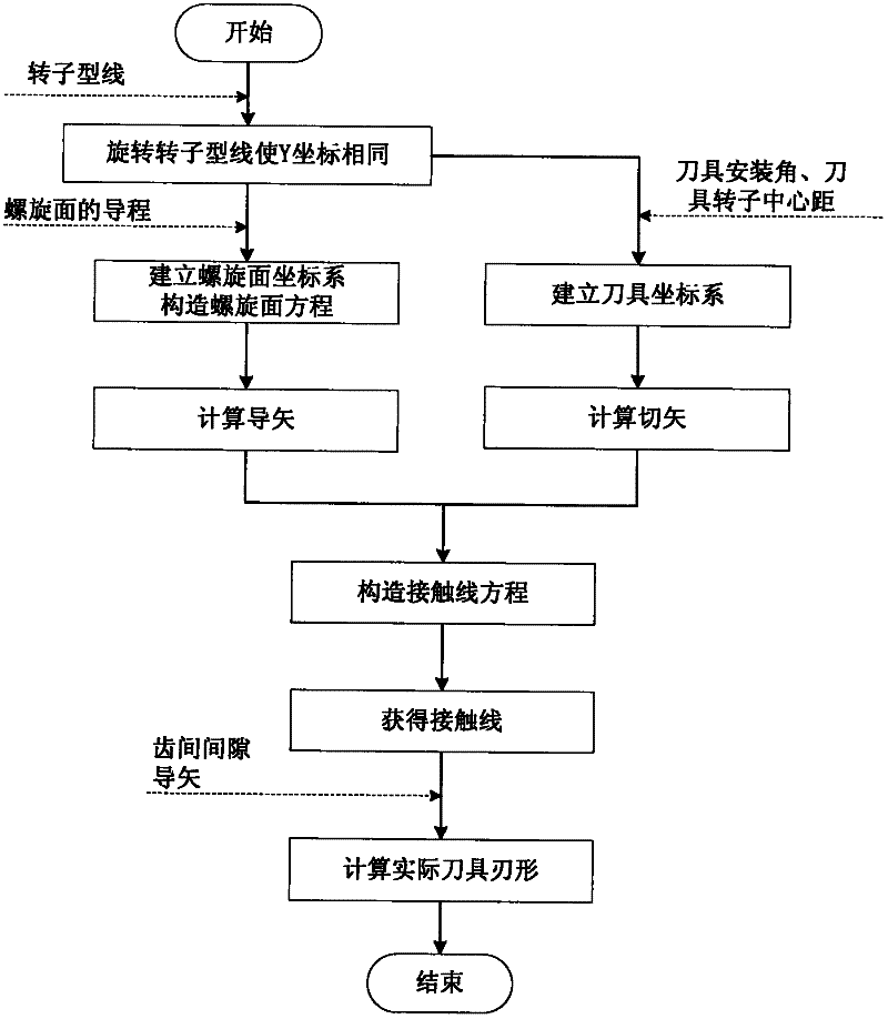

Image

  • Cutter edge modification method for processing helicoid of screw rotor
  • Cutter edge modification method for processing helicoid of screw rotor
  • Cutter edge modification method for processing helicoid of screw rotor

Examples


Embodiment Construction

[0095] Describe the present invention below in conjunction with specific embodiment:

[0096] In this embodiment, the LG7.5 / 8 oil-injected screw air compressor is taken as an example. The rotor length of the compressor is 100 mm, and the male rotor has a torsion angle τ 1z is 300°, the female rotor torsion angle τ 2z is 240°; male rotor lead T 1 120mm, female rotor lead T 2 150mm; center distance A between male rotor and cutter 1c is 267.25mm, the center distance A between the female rotor and the cutter 2c 260.5mm; installation angle Both are 43.7°.

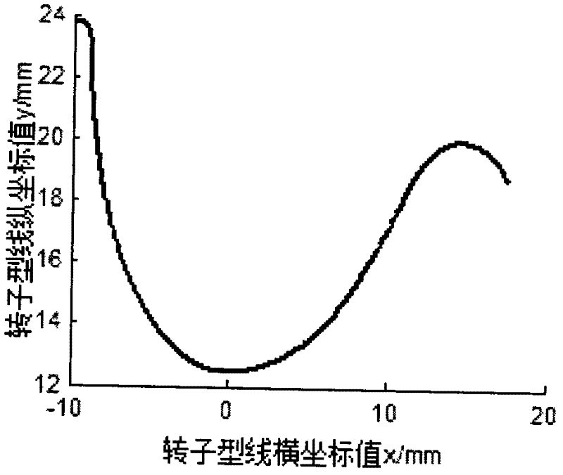
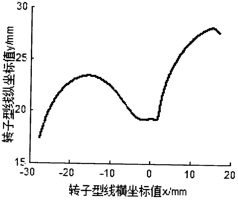
[0097] The rotor profile is given in the form of discrete points, and the corresponding coordinates of the discrete points starting from one end of the rotor profile in the initial coordinate system OOXXYY are ( xxx 1 , yy 1 ), ( xxx 2 , yy 2 ),...,( xxx n , yy n ), as attached figure 2 And attached image 3 shown. attached figure 2 And attached image 3 Corresponding to the molded lines of the female...


PUM


Abstract

The invention provides a cutter edge modification method for processing the helicoid of a screw rotor. The method has the following beneficial effects: the equidistant tooth surfaces of tooth surfaces of a theoretical rotor processed by a grinding wheel or a cutter are obtained through analysis and computation; the equidistant tooth surfaces are not equal in normal gaps of lines of contact; profile gaps are not equal on the end face of the theoretical rotor and the end face of a practical rotor, namely, when the meshing point is farther from the rotor axis, the profile gaps can be enlarged asthe helical angle is enlarged; and such gap distribution ensures that the tooth surfaces of the rotor are insensitive to change of the side gaps of a synchronous rotor or gear, thus reducing the danger that tooth surfaces of the rotor are stuck and being very beneficial to safe operation of machinery.

Description

technical field [0001] The invention relates to the field of cutter blade shape design and correction methods, in particular to a cutter blade shape correction method for machining a helical surface of a screw rotor. Background technique [0002] The screw rotor is a key part of the screw compressor, and its processing quality directly determines the reliability, efficiency and noise level of the compressor. The patent application document with the application number 201110205840.8 discloses a tool blade shape design method for machining the helical surface of a screw rotor. This method is versatile and suitable for the case where the rotor profile is given at any position, and is suitable for any helical surface For the calculation of the blade shape of the tool, there is a clear and simple mathematical transformation between the rotor coordinate system and the tool coordinate system established after the specific rotation transformation. The transcendental equation establi...

Claims


Application Information

Patent Timeline
IPC IPC(8): G06F17/50
Inventor 吴宝海张娟杨建华张莹陈冰何志龙
Owner NORTHWESTERN POLYTECHNICAL UNIV
Learn More