
Light stream calculation system and method

A computing system and optical flow technology, applied in the fields of image processing and computer vision, can solve problems such as unfavorable, poor support of optical flow method, and low general computing ability

Active Publication Date: 2012-06-20
江苏虎甲虫计算技术有限公司
View PDF2 Cites 17 Cited by
  • Summary
  • Abstract
  • Description
  • Claims
  • Application Information

AI Technical Summary

Problems solved by technology

[0005] However, the difficulties in calculating the optical flow field in the embedded environment are: 1. The embedded system needs to process video data in real time, while the general system often stores the data and processes it slowly
Therefore, increasing the complexity of the algorithm in the embedded system will affect the timely processing of data and affect the assumptions, but the general system will not; 2. Due to the limitations of power consumption, volume, cost, etc., the general computing capability of the embedded system is often not high; 3. Most embedded processors have limited floating-point computing capabilities, and cannot well support the optical flow method that requires a large number of floating-point calculations; 4. The optical flow method that uses algorithms to make up assumptions tends to lead to complex algorithms, which is not conducive to the use of hardware acceleration
[0006] The above factors make it easy to fall into a negative cycle when directly adopting the idea under the general platform in the embedded environment: limited video data processed and utilized in a timely manner → weakened assumptions → more complex algorithms → poorer timely processing capabilities, so must A new way of thinking to solve the above problems

Method used


Image

  • Light stream calculation system and method
  • Light stream calculation system and method
  • Light stream calculation system and method

Examples


Embodiment Construction

[0037] In order to make the above objects, features and advantages of the present invention more comprehensible, the present invention will be further described in detail below in conjunction with the accompanying drawings and specific embodiments.

[0038] The detailed description of the present invention is mainly presented by programs, steps, logic blocks, processes or other symbolic descriptions, which directly or indirectly simulate the operation of the technical solutions in the present invention. These descriptions and representations herein are used by those skilled in the art to effectively convey the substance of their work to others skilled in the art.

[0039] The term "one embodiment" or "embodiment" here refers to that specific features, structures or characteristics related to the embodiment can be included in at least one implementation of the present invention. The appearances of "in one embodiment" in various places in this specification do not necessarily al...


PUM


Abstract

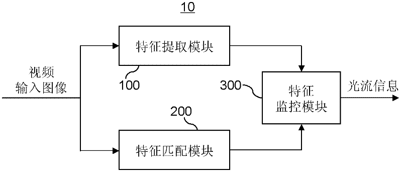
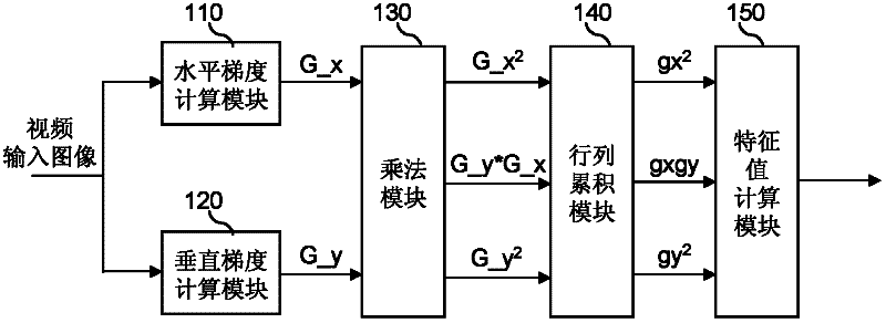
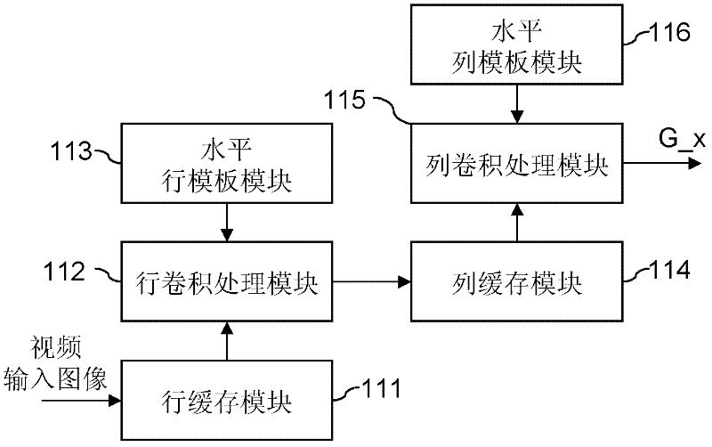
The invention discloses a light stream calculation system and a method. The light stream calculation system comprises a characteristic extraction module, a characteristic matching module and a characteristic monitoring module, wherein the characteristic extraction module sequentially calculates the characteristic values corresponding to the pixel points of an input image; the characteristic matching module sequentially calculates the light stream information corresponding to the pixel points of the input image; and the characteristic monitoring module synchronizes the characteristic values corresponding to the pixel points and the light stream information corresponding to the pixel points, and determines whether to output the light stream information of the pixel points based on the characteristic value corresponding to a pixel point. In the invention, a stream type hardware calculation mode is adopted to realize characteristic matching and characteristic extraction of the pixel points of the input image; following the input of each pixel point of the image, the characteristic value and light stream information corresponding to each pixel point can be finished in a stream manner; and therefore, dense light stream information can be provided. Moreover, due to the indication of the characteristic value, only the light stream of the pixel points with good characteristics can be output, and thus the real motion conditions of the target can be reflected relatively well.

Description

【Technical field】 [0001] The invention relates to the fields of image processing and computer vision, in particular to an optical flow calculation system and method. 【Background technique】 [0002] As we all know, the optical flow field is the corresponding embodiment of the motion field of objects moving in space on the image plane. It can be used to approximate the real motion field in space, and it is suitable for the case of camera motion. The optical flow field not only carries the motion information of the object, but also carries the information about the three-dimensional structure of the scene. Through optical flow field calculation, moving objects can be detected without knowing the scene information. Therefore, the optical flow field calculation method (or optical flow method) has an extremely important basic position in the field of pattern recognition, computer vision and other image processing. [0003] However, the biggest disadvantage of the current optical...

Claims


Application Information

Patent Timeline
IPC IPC(8): G06K9/00G06T7/20
Inventor 柴志雷任小媛高卫东梁久祯张平钟传杰刘基宏潘如如
Owner 江苏虎甲虫计算技术有限公司
Learn More