
Directed dipole antenna for underground earth-probing radar

A technology for dipole antennas and geological exploration, applied in antennas, antenna arrays, radiating element structures, etc., can solve problems such as long duration, difficult system rotation, large pulse waveform tailing, etc., and achieve production and use costs The effect of low frequency, wide operating frequency and large detection range

Inactive Publication Date: 2012-06-20
UNIV OF ELECTRONICS SCI & TECH OF CHINA
View PDF4 Cites 9 Cited by
  • Summary
  • Abstract
  • Description
  • Claims
  • Application Information

AI Technical Summary

Problems solved by technology

When the antenna is used in the well, the antenna system needs to be rotated mechanically, otherwise it can only work in one direction, and when the antenna is located below the depth of 1000m, the rotation of the system is difficult to achieve; in addition, the antenna uses a right-angle reflector, and its structure Although it is simple, it will have a serious impact on the phase of the pulse waveform reflected by the reflector. In addition, the terminal resistance is used to load, the in-band fluctuation is large, the bandwidth is narrow, the ratio of the main peak to the secondary peak of the antenna radiation pulse waveform is not obvious, and the pulse waveform is tailed It is large and lasts for a long time, which seriously affects the extraction of the target echo; especially when the target echo is completely submerged in the direct coupling wave tailing oscillation, the echo signal cannot be extracted

Method used


Image

  • Directed dipole antenna for underground earth-probing radar
  • Directed dipole antenna for underground earth-probing radar
  • Directed dipole antenna for underground earth-probing radar

Examples


Embodiment Construction

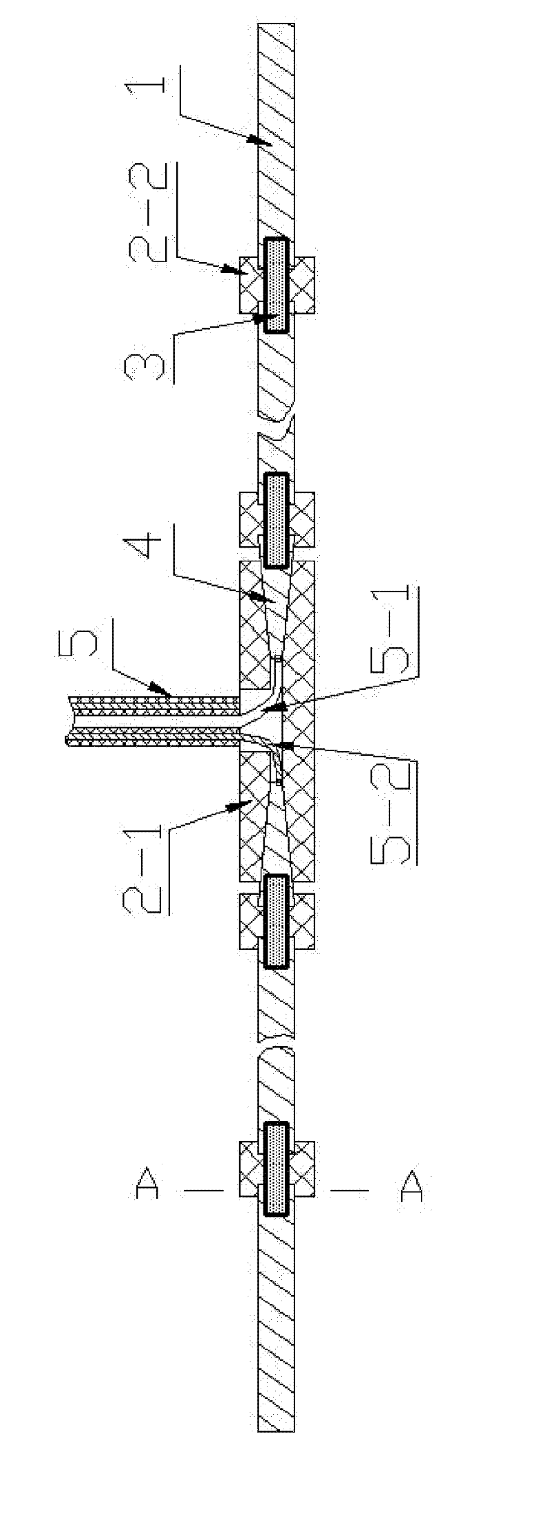
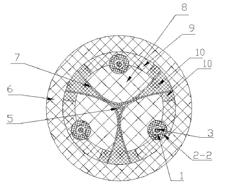
[0014] In this embodiment: the housing 6 adopts a glass fiber reinforced plastic cylinder, the length is 628mm, and the inner and outer diameters are Φ69mm and Φ89mm respectively; , 40mm long aluminum cylinder antenna section 1, two monopole antenna heads 4 are 20mm apart; each antenna head 4 adopts a conical frustum antenna head, the front (inner) end diameter is Φ2mm, the rear end diameter is Φ6mm, and the length is 20mm , the material is metal aluminum; each loading resistor 3 is a cylindrical resistor with a diameter of Φ3.5mm and a length of 15mm. The resistance values ​​of the resistors are 3 ohms, 6 ohms, 9 ohms, 15 ohms, 25 ohms, and 60 ohms from the inside to the outside; the fixed sleeves of each antenna section are 2-2, the length is 9mm, the outer diameter is Φ12mm, and the loading resistor 4 and the antenna The inner diameters of the joints of Section 1 are Φ3.5mm and Φ6mm, and the material is insulating plastic; the material of the antenna head connection and fix...


PUM


Abstract

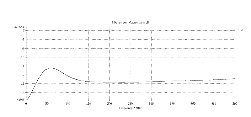
The invention belongs to a directed dipole antenna for an underground earth-probing radar. The directed dipole antenna comprises an antenna shell, three dipole antennas, three reflecting plates, a low-loss dielectric, a high-loss dielectric, an insulation dielectric and a cable outlet, wherein the three dipole antennas are arranged in the shell; the three reflecting plates are arranged correspondingly back to back around the center lines of the dipole antennas; the low-loss dielectric, the high-loss dielectric and the insulation dielectric are respectively filled among the dipole antennas, the reflecting plates and the shell; each dipole antenna comprises two monopole antennas; and a loading resistor is respectively arranged between the antenna head and antenna section and between the antenna sections of each monopole antennae. The invention has the characteristics that the diameter is small, probing in a deep well under 1000m can be realized, the emission and receiving frequencies are low, the probing range is wide, the working band is wide, the s11 curve in a frequency range of 0-500M is very flat, fluctuation in a frequency range of 40M-500M under -10dB is only 1.6dB, the wave main-to-side lobe ratio is 2.5, the tail oscillation is very small, the tailing of the main peak after 10ns is less than 1 / 40 of the main peak, the production and use cost of the overall system is low, and the like.

Description

technical field [0001] The invention belongs to a directional dipole antenna for geological detection radar, in particular to a directional dipole antenna for underground geological detection radar. Deep detection is carried out in order to obtain accurate data such as the geological conditions in the deep strata or the characteristics and orientation of the resources to be measured, so as to provide scientific basis for relevant management and decision-making departments. Background technique [0002] Geological detection radar is an efficient shallow geophysical detection technology. It transmits high-frequency pulsed electromagnetic waves, uses the difference in electrical parameters of the underground medium, and analyzes and infers the structure and material of the underground medium according to the characteristics of the amplitude and phase of the echo. feature. The methods generally adopted by geological detection radar are carried out on the surface of the ground o...

Claims


Application Information

Patent Timeline
Patent Type & Authority Applications(China)
IPC IPC(8): H01Q21/00H01Q19/13H01Q1/36
Inventor 赵青唐剑明马春光刘述章
Owner UNIV OF ELECTRONICS SCI & TECH OF CHINA
Learn More