A weak signal detection amplification system and method based on an optoelectronic oscillator

A photoelectric oscillator and amplifying system technology, applied in the field of microwave photonics, can solve the problems of small detection frequency range, loss, and insignificant amplification effect, and achieve the effect of improving the gain effect and widening the detection range.

Active Publication Date: 2019-06-04
INST OF SEMICONDUCTORS - CHINESE ACAD OF SCI
View PDF5 Cites 19 Cited by
  • Summary
  • Abstract
  • Description
  • Claims
  • Application Information

AI Technical Summary

Problems solved by technology

However, in the existing methods, the multimode photodetector based on the injection-locked OEO intracavity electric band-pass filter for weak signals can only amplify the signal in the frequency range of 1-6GHz by 8dB, and the detection sensitivity It has reached -83dBm, but there is a problem that the detection frequency range is small and the amplification effect is not obvious; the tunable photodetector system based on Bragg grating is used to detect and amplify radio frequency signals, which can detect the frequency range of 1.5 ~ 5GHz The signal is amplified by 10dB, the detection sensitivity reaches -91dBm, and the measurement error of the detection frequency reaches 100MHz. However, the frequency range that this method can detect is limited by the grating to only 5.5GHz, and this method uses the loss of the first-order phase modulation The sideband is used to realize the conversion from phase modulation to intensity modulation to achieve the amplification of weak signals. In theory, there is an amplification bottleneck.

Method used


Image

  • A weak signal detection amplification system and method based on an optoelectronic oscillator
  • A weak signal detection amplification system and method based on an optoelectronic oscillator
  • A weak signal detection amplification system and method based on an optoelectronic oscillator

Examples


Embodiment Construction

[0043]In order to make the object, technical solution and advantages of the present invention clearer, the present invention will be further described in detail below in conjunction with specific embodiments and with reference to the accompanying drawings.

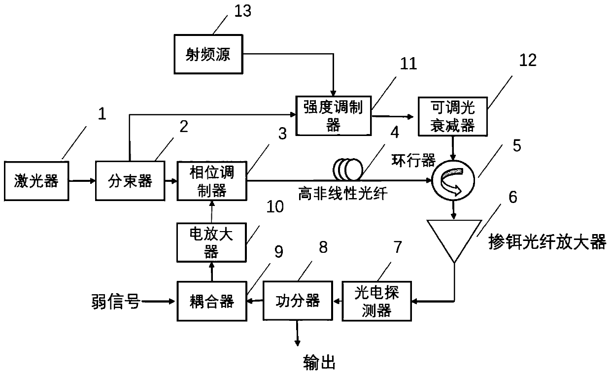
[0044] According to one aspect of the present invention, a kind of weak signal detection amplification system based on photoelectric oscillator is provided, such as figure 1 as shown, figure 1 A schematic structural diagram of a photoelectric oscillator-based weak signal detection and amplification system provided for an embodiment of the present invention. The photoelectric oscillator-based weak signal detection and amplification system includes:

[0045] Laser 1, beam splitter 2, phase modulator 3, highly nonlinear fiber 4, circulator 5, photodetector 7, power splitter 8, coupler 9, electrical amplifier 10, intensity modulator 11, adjustable optical attenuation device 12 and radio frequency source 13, wherein:

[0046]...


PUM


Abstract

The invention provides a weak signal detection amplification system based on an optoelectronic oscillator and a detection amplification method thereof, and belongs to the technical field of microwavephotonics. The weak signal detection amplification system based on the optoelectronic oscillator comprises a laser, a beam splitter, a phase modulator, a high-nonlinearity optical fiber, a circulator,a photoelectric detector, a power divider, a coupler, an electric amplifier, an intensity modulator, an adjustable optical attenuator and a radio frequency source. Wherein the laser is connected withthe beam splitter, the beam splitter is respectively connected with the phase modulator and the intensity modulator, and the phase modulator, the circulator, the photoelectric detector, the power splitter, the coupler and the electric amplifier are sequentially connected end to end to form a loop; Wherein the intensity modulator, the variable optical attenuator and the circulator are sequentiallyconnected, the radio frequency source is connected to the intensity modulator, and the phase modulator is connected with the circulator through a high-nonlinearity optical fiber. By adjusting the radio frequency source and the adjustable optical attenuator, rapid and high-precision weak signal detection and amplification can be realized.

Description

technical field [0001] The invention relates to the technical field of microwave photonics, in particular to a system and method for detecting and amplifying weak signals based on a photoelectric oscillator. Background technique [0002] Fast frequency measurement plays an increasingly important role in systems such as radar and electronic stations, but the premise of fast frequency measurement is that the system can distinguish the received signal, especially for the detection of weak signals. It is particularly important to detect and amplify the signal with a wide frequency band and high power. For the detection and amplification of weak signals, in its electronic solution, very narrow filters and amplifiers are used, but the realization of this solution is particularly difficult because of the technical development and the noise introduced by the electric amplifier. Microwave photonics method is adopted by more and more people because of its advantages of large bandwidt...

Claims


Application Information

Patent Timeline
Patent Type & Authority Applications(China)
IPC IPC(8): H04B10/291H04B10/2575
Inventor 李明王光强郝腾飞祝宁华
Owner INST OF SEMICONDUCTORS - CHINESE ACAD OF SCI
Why Eureka
Try Eureka