Method for realizing the intelligent tour-inspection of power tower based on miniature multi-rotor unmanned helicopter

A multi-rotor unmanned, intelligent inspection technology, applied in the direction of controlling the starting method, aircraft parts, electrical components, etc., can solve the problems of not being able to effectively approach the observation target, the convenience of operation, and the large size of the aircraft. High efficiency, ensure safety, good safety effect

Inactive Publication Date: 2012-06-20
NORTH CHINA ELECTRIC POWER UNIV (BAODING)
4 Cites 79 Cited by

AI-Extracted Technical Summary

Problems solved by technology

Although this method improves the inspection efficiency and reduces the inspection difficulty compared with the traditional manual inspection method, due to the large size of the aircraft it uses, in order to ensure the safe operation of the transmission line, it is often unable to effectively approach the observation target
Moreover, due ...

Abstract

The invention discloses a method for realizing the intelligent tour-inspection of a power tower based on a miniature multi-rotor unmanned helicopter, and belongs to the technical field of tour-inspection of transmission lines. The method comprises the following steps of: tower modeling, inspection viewpoint planning, autonomous navigation, data acquisition and failure analysis, wherein the tower modeling step comprises a data acquisition process, a tower positioning process, a security zone division process and a security zone evaluation process; the inspection viewpoint planning step refers to a process of solving an optimal observation viewpoint according to related constraint conditions; the autonomous navigation step comprises a basic navigation sub-step and an accurate navigation sub-step; the data acquisition step refers to a process of transmitting related data back to a ground station by using the miniature multi-rotor unmanned helicopter; and the failure analysis step refers to a process of performing analysis, judgment and diagnosis according to the data transmitted back to the ground station by tour-inspection and decision making personnel. The method has the advantages of high safety, detection accuracy, tour-inspection efficiency and flexibility, low cost and high operability.

Application Domain

Actuated automaticallySwitchgear

Technology Topic

Image

  • Method for realizing the intelligent tour-inspection of power tower based on miniature multi-rotor unmanned helicopter
  • Method for realizing the intelligent tour-inspection of power tower based on miniature multi-rotor unmanned helicopter
  • Method for realizing the intelligent tour-inspection of power tower based on miniature multi-rotor unmanned helicopter

Examples

  • Experimental program(1)

Example Embodiment

[0038] The present invention will be described in further detail below in conjunction with the drawings:
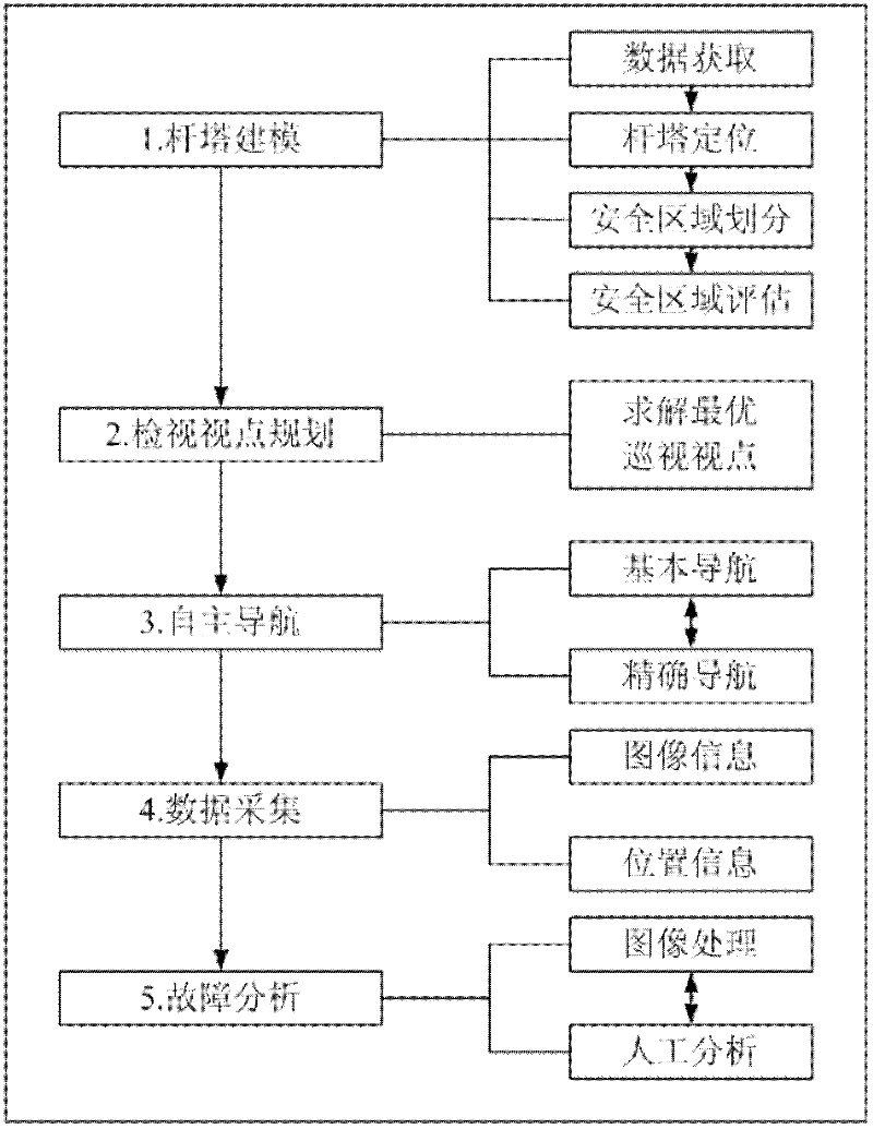
[0039] Such as figure 1 As shown, the intelligent inspection method for power towers based on multi-rotor drones. It is divided into the following steps: tower modeling, viewing point planning, autonomous navigation, data collection and failure analysis.
[0040] Tower modeling is divided into data acquisition process, tower positioning process, safety zone division process and safety zone assessment process;
[0041] The data acquisition process is: obtain the basic structure of the tower through the engineering drawings provided by the transmission line designer, and on this basis, obtain more detailed structure features of the tower by means of vision or laser testing, and complete the three-dimensional reconstruction process;
[0042] The pole positioning process is: according to the map and GPS positioning system, the exact position of each pole of the transmission line to be detected is positioned;
[0043] The process of dividing the safe area is as follows: in accordance with the “Technical Guidelines for Helicopter Patrols on Overhead Transmission Lines”, a standard for the electric power industry of the People’s Republic of China, a safe flight area is delineated in advance on the periphery of each tower (that is, images can be captured smoothly during the aircraft inspection process. It will touch the reliable observation range of the power line components. When the miniature multi-rotor unmanned helicopter is flying in this range, it must not touch any power transmission tower components and wires, and it shall not cause adverse effects on the normal operation of the power transmission line; Target observation has a better viewing angle).
[0044] Such as Figure 2a , Figure 2b , Figure 2c Shown are three views of the safe flight area. In the safe flight areas 1 and 7, the micro multi-rotor unmanned helicopter can observe the towers, wires, grounding devices and infrastructure; in the safe flight areas 2, 3, 5, and 6 In, the miniature multi-rotor unmanned helicopter can observe insulators, fittings, auxiliary facilities and wires. According to the statistical results of the frequency of failures of the power transmission equipment in each safe flight area and the inherent service life, different inspection weights are assigned to the obtained safe flight areas. For example, the key inspection areas (safe flight areas 2, 3, 5, 6) and general inspection areas (safe flight areas 1, 4, 7) are divided. will Figure 2a , Figure 2b , Figure 2c The safe flight area in is regarded as a curved surface in space. After discretizing it, a grid can be obtained. The vertex represents an observation point that the micro multi-rotor unmanned helicopter can reach, and the arc represents the possibility of the micro multi-rotor unmanned helicopter. Flight path, such as Figure 3a , Figure 3b Shown.
[0045] The safety area assessment process is as follows: further evaluate the resulting safe flight area according to the frequency and inherent service life of each device in the safe flight area, so as to determine the different weights of the safe flight area (such as key inspection areas, general inspections) Area, etc.).
[0046] The viewing viewpoint planning refers to the process of optimizing the viewing viewpoint in the above-mentioned safe flight area;
[0047] Observation point of view refers to the observation position and viewing angle of the micro multi-rotor unmanned helicopter in space, that is, the position coordinates of the micro multi-rotor unmanned helicopter itself and the orientation of the visual sensor. Specifically, the micro multi-rotor unmanned helicopter is inspecting In the process, it is necessary to visit each area in sequence to complete the inspection of the entire tower (visible light image collection, infrared image collection, collection of electrical tower and surrounding environment information), and observe the power transmission equipment contained in the area in the area. However, the choice of observation viewpoints within the area is flexible. How to choose the corresponding observation viewpoints to ensure the quality of observation and flight time is a problem to be solved in viewpoint planning. Predetermine the safe flight area and all feasible observation points of the micro multi-rotor unmanned helicopter through the established connection graph, and use the optimization method to effectively cover the parts to be inspected, taking the flight efficiency, observation quality and inspection tasks as constraints The best observation point of view;
[0048] The miniature multi-rotor unmanned helicopter plans its trajectory and observation angle according to the results of tower modeling. Such as Figure 2a , Figure 2b , Figure 2c As shown, during the inspection process, the miniature multi-rotor unmanned helicopter traverses the safe flight area 1 to the safe flight area 7 in the order of the divided safe areas, and each area has many different observation points. According to the data obtained by modeling the tower, each observation point has different observable power transmission equipment and different observation angles.
[0049] Such as Figure 3a , Figure 3b As shown, the black triangle represents the observation point of view. During the inspection, the micro multi-rotor unmanned helicopter starts from an observation point in area 1. When passing through areas 2 to 7, the micro multi-rotor unmanned helicopter is on an optimal path On a flight like Figure 3a , Figure 3b Shown in the broken line to achieve the best inspection results. The broken line indicates that connecting these key observation points to form an optimal path. Around each observation point of view, the miniature multi-rotor unmanned helicopter also needs to fine-tune the observation angle according to the relative position of itself and the observation target to ensure that the observation point of power transmission equipment can be fully captured.
[0050] At this time, the micro multi-rotor unmanned helicopter began to conduct inspections. Since the safety area assessment has been carried out, the inspection flight process at this time has a high degree of safety. The micro multi-rotor unmanned helicopter completes the control of the flight attitude of the micro multi-rotor unmanned helicopter through the flight control algorithm running on the processor and the sensor feedback data such as flight speed, angular velocity and altitude. First, through the GPS positioning system, the miniature multi-rotor unmanned helicopter estimates the relative position between the flight position and the planned observation point, and adjusts the flight path. Due to the limitation of the accuracy of the GPS positioning system, there is still a certain error between the observation position and the predetermined observation position at this time, so further precise navigation is required. When the micro multi-rotor unmanned helicopter flies near the predetermined observation point, the space relationship between the tower model and the position of the micro multi-rotor unmanned helicopter, combined with the measurement value of the GPS positioning system, is used to further calibrate the micro multi-rotor. The observation point of view of the helicopter to ensure that it accurately visits the predetermined observation position.
[0051] The miniature multi-rotor unmanned helicopter starts autonomous navigation from safe flight zone 1 according to the above steps, combines sensor feedback data, continuously estimates the relative position of itself to the predetermined observation point and tower, and visits safe flight zone 1 to safe flight zone 7 in sequence All planned optimal observation points.
[0052] The miniature multi-rotor unmanned helicopter collects image data through visible light cameras and infrared cameras at a predetermined observation position, and records the environmental information and flight status of each mission point. While the miniature multi-rotor unmanned helicopter conducts inspections, it transmits the collected data back to the ground station through the wireless data link. Ground inspection and decision-making personnel can be equipped with an imaging device (such as a display or a portable handheld terminal, etc.) capable of receiving wireless signals to observe the situation on the tower in real time.
[0053] Fault analysis refers to: inspection and decision-making personnel based on the visible light and infrared thermal image image data, visible light and infrared thermal image video data, GPS location information and flight status information transmitted back to the ground station, image processing, video analysis and With the assistance of fault diagnosis and other modules, targeted analysis, discrimination and diagnosis are carried out to determine the overall health of the overhead transmission line tower, and assist the transmission line maintenance department to effectively implement the maintenance and troubleshooting of the overhead transmission line tower.

PUM

no PUM

Description & Claims & Application Information

We can also present the details of the Description, Claims and Application information to help users get a comprehensive understanding of the technical details of the patent, such as background art, summary of invention, brief description of drawings, description of embodiments, and other original content. On the other hand, users can also determine the specific scope of protection of the technology through the list of claims; as well as understand the changes in the life cycle of the technology with the presentation of the patent timeline. Login to view more.

Similar technology patents

Application of giant salamander mucus in preparation of adhesive

InactiveCN104740678ANatural ingredientsGood securitySurgical adhesivesChemistryTissue adhesives
Owner:CHONGQING KUIXU BIOLOGICAL SCI & TECH +2

Indirect ELISA kit for detecting avian infectious bronchitis virus antibody

InactiveCN102093999AGood securityGood antigenicityRecombinant DNA-technologyMaterial analysisProtein servingsSorbent
Owner:POULTRY INST SHANDONG ACADEMY OF AGRI SCI

Classification and recommendation of technical efficacy words

  • Good security
  • Ensure safety

Computer information safe method

InactiveCN101231682AGood securityImprove recognition efficiency and accuracyInternal/peripheral component protectionRedundant operation error correctionSystem safetyProgram behavior
Owner:李贵林

Transaction verification method and system based on block chain

ActiveCN106548330APrevent balance leakageEnsure safetyPayment protocolsPayment circuitsVerification systemComposite number
Owner:ONE CONNECT SMART TECH CO LTD SHENZHEN
Why Eureka
Try Eureka