Capped end polishing machine

A technology of polishing machine and polishing mechanism, which is applied in the direction of surface polishing machine tools, grinding/polishing equipment, metal processing equipment, etc., can solve the problems that the surface finish uniformity of the head cannot be guaranteed, and achieve the elimination of surface finish uniformity and efficiency High, good polishing quality

Inactive Publication Date: 2012-06-27
ZHEJIANG KIN SHINE TECH
View PDF6 Cites 19 Cited by
  • Summary
  • Abstract
  • Description
  • Claims
  • Application Information

AI Technical Summary

Problems solved by technology

[0003] The purpose of the present invention is to provide a head polishing machine with simple structure, convenient operation and good polishing effect, which solves the defect that manual operation cannot ensure the uniformity of the surface finish of the head

Method used


Image

  • Capped end polishing machine
  • Capped end polishing machine
  • Capped end polishing machine

Examples


Embodiment

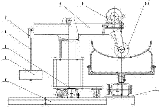
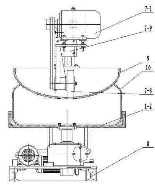
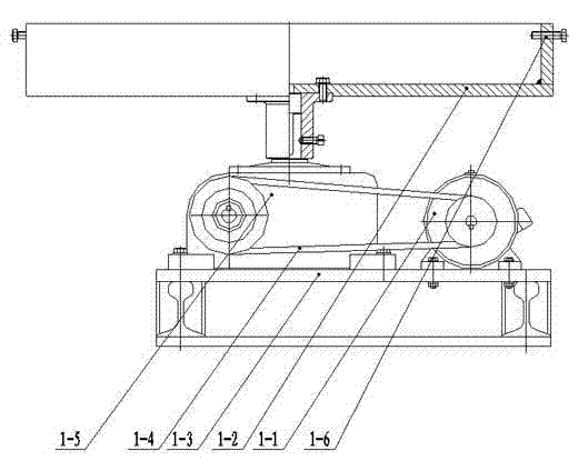
[0024] like figure 1 and figure 2 The head polishing machine shown is composed of a track 8, a traveling mechanism 3 that can move horizontally along the track 8, a head turning mechanism 1, an automatic lifting system and a polishing mechanism 7, which are used to clamp the head and drive the head to rotate The head rotation mechanism 1 is set on the side of the track 8, and the automatic lifting system that drives the polishing mechanism 7 to perform feeding motion along the inner arc surface of the head includes a cantilever mechanism 6 and a counterweight 2. The cantilever mechanism passes through the support 6-3 Be fixed on the running gear 3 and be hinged with the support 6-3. One end shaft of the cantilever mechanism 6 is connected with a fork rod 5, the fork rod 5 is connected with the counterweight 2 through the double-ended screw 4, and the counterweight is fixed on the lower end of the double-ended screw 4; the other end of the cantilever mechanism 6 is connected ...


PUM


Abstract

The invention relates to a polishing machine, in particular to a capped end polishing machine for polishing capped ends, belonging to the field of mechanical equipment. The capped end polishing machine comprises a rail, a running mechanism capable of horizontally moving along the rail, a capped end rotation mechanism, an automatic lifting system and a polishing mechanism, wherein the capped end rotation mechanism for clamping a capped end and driving the capped end to rotate is arranged on one side of the rail; the automatic lifting system for driving the polishing mechanism to perform feed motion along the inner circular-arc face of the capped end comprises a cantilever mechanism and a balancing weight; one end of the cantilever mechanism is connected with the balancing weight, and the other end of the cantilever mechanism is fixed with the polishing mechanism; and the cantilever mechanism is fixed on the running mechanism through a supporting seat and is hinged with the supporting seat. The polishing machine disclosed by the invention has a reasonable structure and a high efficiency, is simple and convenient to operate, greatly improves the environmental condition for operators, has high polishing quality, and completely eliminates the defect that hand operation cannot ensure the uniformity of the smoothness of all surfaces.

Description

technical field [0001] The invention relates to a polishing machine, in particular to a head polishing machine for polishing a head, which belongs to the field of mechanical equipment. Background technique [0002] In the production of pressure vessels and steel cylinders, polishing requirements are often encountered on the inner surface of the head. At present, manual polishing is generally used, which is time-consuming and labor-intensive. The working environment is very harsh and the polishing quality is poor. The existing traditional polishing is difficult, takes a long time, consumes a lot of consumables, and manual operation cannot guarantee the uniformity of surface finish everywhere. Contents of the invention [0003] The purpose of the present invention is to provide a head polishing machine with simple structure, convenient operation and good polishing effect, which solves the defect that manual operation cannot ensure the uniformity of the surface finish of the ...

Claims


Application Information

Patent Timeline
Patent Type & Authority Applications(China)
IPC IPC(8): B24B29/02
Inventor 傅伟阳俞世桥
Owner ZHEJIANG KIN SHINE TECH
Why Eureka
Try Eureka