
Method and device for regulating linear density of glass fiber through correcting drawing flow in real time

A glass fiber and linear density technology, which is applied in glass manufacturing equipment, manufacturing tools, etc., can solve the problems of temperature sensor accuracy influence, temperature sensor is easy to age, and glass fiber linear density cannot be guaranteed to remain unchanged, so as to achieve accurate adjustment and accurate The effect of drawing flow

Active Publication Date: 2012-06-27
JUSHI GRP CO
View PDF4 Cites 4 Cited by
  • Summary
  • Abstract
  • Description
  • Claims
  • Application Information

AI Technical Summary

Problems solved by technology

This method has the following disadvantages: 1. The leaky plate works at high temperature, and the temperature sensor inside the leaky plate directly touches the high-temperature glass liquid, which makes the temperature sensor easy to age, thereby affecting the accuracy of the temperature sensor; 2. Even if this method can control the temperature stability At the ideal temperature, the glass fiber linear density cannot be guaranteed to remain unchanged, because there are other factors that affect the glass fiber linear density

Method used


Image

  • Method and device for regulating linear density of glass fiber through correcting drawing flow in real time
  • Method and device for regulating linear density of glass fiber through correcting drawing flow in real time
  • Method and device for regulating linear density of glass fiber through correcting drawing flow in real time

Examples


Embodiment Construction

[0025] The present invention will be further described in detail below in conjunction with the accompanying drawings and examples. The following examples are explanations of the present invention and the present invention is not limited to the following examples.

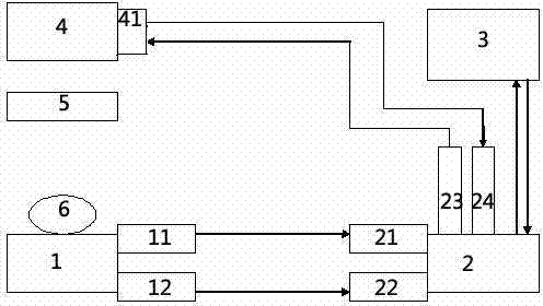
[0026] like figure 1 and figure 2 As shown, the method for adjusting the linear density of glass fibers by correcting the drawing flow in real time in this embodiment is characterized in that it includes the following steps:

[0027] a. Make the glass liquid pass through the small hole formed on the bushing 5 to form glass fibers, and wind the glass fibers with rotating winding wires to make yarn clusters 6;

[0028] b, generating a signal representing the weight of the yarn cluster 6;

[0029] c. In response to the weight signal of the yarn cluster 6, referring to the set weight value, a weight difference signal indicating the degree of difference between the weight of the yarn cluster 6 and the set weight is ge...


PUM


Abstract

The invention provides a method and a device for regulating linear density of glass fiber through correcting drawing flow in real time and belongs to a glass fiber production industry. The method comprises the following steps of: passing molten glass through a small hole formed on a bushing plate so as to form glass fiber; winding the glass fiber with a rotary winding wire to prepare a yarn cluster; generating a signal representing the weight of the yarn cluster; responding the weight signal of the yarn cluster, and generating a weight difference signal by referring to a set weight value; responding the weight difference signal, and generating a drawing flow correcting signal through comparing a characteristic curve or a characteristic database; and generating a combination feedback signal indicating the drawing flow which tends to be obtained through regulation according to the drawing flow correcting signal and the reference set drawing flow, and responding the combination feedback signal to correct the drawing flow so that the linear density of the glass fiber is regulated and the combination feedback signal value is used as the next set drawing flow value. Through using the method and the device, the fluctuation of the linear density of the glass fiber due to the fluctuation of the temperature of the bushing plate can be regulated, and the fluctuation of the linear density of the glass fiber due to variation of drawing flow can also be regulated.

Description

technical field [0001] The invention discloses a method and a device for adjusting the linear density of glass fibers by correcting the drawing flow in real time, belonging to the glass fiber manufacturing industry. Background technique [0002] Glass fiber is widely used in all walks of life. In order to ensure the weight of glass fiber produced, the linear density of glass fiber must be controlled. The main factors affecting the linear density of glass fiber are: first, the temperature of the bushing, which affects the temperature of the bushing. The temperature of the molten glass affects the viscosity of the molten glass, which in turn affects the linear density of the glass fiber; the second is the winding speed of the wire drawing machine. The product will increase the outer diameter of the bobbin, so the winding speed of the bobbin must be adjusted to adjust the drawing speed of the wire drawing machine to ensure the drawing speed, and the drawing speed directly affec...

Claims


Application Information

Patent Timeline
Patent Type & Authority Applications(China)
IPC IPC(8): C03B37/022C03B37/07C03B37/03
Inventor 凌晓强沈建兴
Owner JUSHI GRP CO
Learn More