Transmission device of roll brush shaft for sweeper truck

A shaft transmission device and road sweeper technology, which is applied in road cleaning, construction, cleaning methods, etc., can solve the problems of reduced use stability, increased difficulty, and increased failure risk, so as to reduce processing difficulty, improve assembly work efficiency, Avoid rigging complex effects

Inactive Publication Date: 2012-06-27
QINGTE GRP
View PDF6 Cites 0 Cited by
  • Summary
  • Abstract
  • Description
  • Claims
  • Application Information

AI Technical Summary

Problems solved by technology

The original roller brush shaft transmission device is connected by welding two sleeves. Due to the limitation of space layout and the influence of manufacturing process, only one end of welding can be used. It is more difficult to ensure the coaxiality and welding strength. Therefore, The stability of its use is greatly reduced, and the risk of failure is also increased

Method used


Image

  • Transmission device of roll brush shaft for sweeper truck
  • Transmission device of roll brush shaft for sweeper truck

Examples


Embodiment Construction

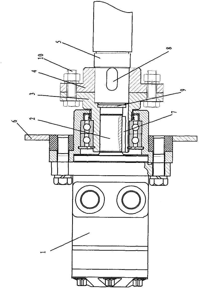
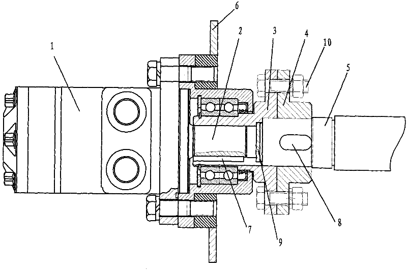
[0013] Such as figure 1 As shown, the present invention is a roller brush shaft transmission device for a road sweeper, including a housing 6, characterized in that: the housing 6 is provided with a hydraulic motor 1, and the hydraulic motor 1 is connected to the motor shaft 2 and the motor shaft 2. The flange plate I 3 is connected to the flange plate I 3 through the key I 7; the flange plate I 3 and the flange plate II 4 are fixedly connected; the flange plate II 4 is connected to the roller brush shaft 5 through the key II 8. The flange I 3 is fixedly connected to the flange II 4 by bolts 10. The flange I 3 is welded with a partition 9 for separating the two cavities. When working, the motor shaft is the drive shaft. The flanges I and II are respectively connected to the motor shaft and the roller brush shaft by keys; the roller brush shaft is inserted between the flanges I and II to play the role of flange connection stop, and bolts are used The connection is fixed to rea...


PUM


Abstract

The invention discloses a transmission device of a roll brush shaft for a sweeper truck, which comprises a casing, wherein a hydraulic motor connected with a motor shaft is arranged on the casing, and the motor shaft is connected with a flange plate I through a key I; the flange plate I is fixedly connected with a flange plate II; and the flange plate II is connected with the roll brush shaft. According to the invention, the motor shaft is connected with the roll brush shaft in an assembling manner so that the roll brush can be disassembled conveniently and the disadvantages of poor welding and fixing stability and complex assembling can be overcome; and the roll brush shaft is matched with the flange plates I and II to realize locating and position limiting function, separately processing of any spigot is not needed, the installation is simple, the processing difficulty is reduced, and the assembling efficiency is improved.

Description

Technical field [0001] The invention relates to a transmission device, in particular to a roller brush shaft transmission device for a road sweeper, belonging to the field of automobiles. Background technique [0002] The suction port of the sweeper with roll sweeper is applied to the eight-ton wet and dry sweeper, placed behind the left and right sweepers. When working, the left and right sweeping brush sweeps the garbage to the middle suction port for suction operation. After the roll brush is placed in the suction port, it rotates to realize the rolling sweep, and sweeps the leaked garbage to the suction port again to achieve secondary suction to ensure Improve the suction efficiency. The original roller brush shaft transmission device is connected by two-sleeve welding. Due to the limitation of the space layout and the production process, only one end can be welded. This increases the difficulty of ensuring the coaxiality and the welding strength. Its use stability is great...

Claims


Application Information

Patent Timeline
IPC IPC(8): E01H1/05
Inventor 纪建奕李守欣李国莹
Owner QINGTE GRP
Why Eureka
Try Eureka