Self-aligning permanent magnet magnetic bearing

A magnetic bearing and permanent magnet force technology, applied in the direction of bearings, shafts and bearings, mechanical equipment, etc., can solve the problems of difficulty in promotion, external power consumption, and inability to achieve the effect of no energy consumption.

Inactive Publication Date: 2013-07-10
魏伯卿
View PDF6 Cites 0 Cited by
  • Summary
  • Abstract
  • Description
  • Claims
  • Application Information

AI Technical Summary

Problems solved by technology

[0002] It is a very good thing to use the permanent magnetic force to isolate the inner and outer ring contact of the bearing to reduce friction and energy loss to improve the bearing efficiency, because the permanent magnetic force has high energy and the magnetic force of some permanent magnet blocks does not attenuate basically. , but in actual use, the bearing will always be biased to one side, so that the inner and outer rings of the bearing are in contact with friction and cannot achieve the purpose of complete suspension rotation; there are many patents at home and abroad to improve its bias to one side, but they are all achieved by adding electromagnetic coils The magnetic force is used to adjust its offset. This external power supply not only consumes energy, but also has adverse factors such as volume effects, so it is difficult to achieve large-scale promotion; how to find a mechanical internal automatic adjustment without external power supply? The method of rotational offset is the prerequisite for the wide application of magnetic bearings

Method used


Image

  • Self-aligning permanent magnet magnetic bearing
  • Self-aligning permanent magnet magnetic bearing
  • Self-aligning permanent magnet magnetic bearing

Examples


Embodiment Construction

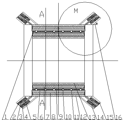
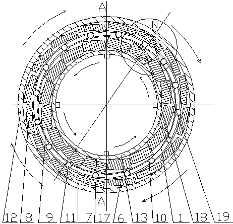
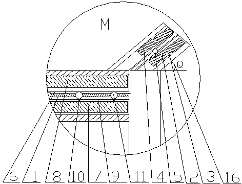
[0024] exist figure 1 There are two implementation structures in the embodiment shown in —7: one is that the permanent magnet block 8 of the outer ring of the bearing is fixed but the angle can be adjusted manually, and the permanent magnet block 7 of the inner ring of the bearing can be pushed by the steel ball between the inner and outer rings to rotate and make The A-type structure in which the magnetic line density changes, and the other is that the permanent magnet block 7 of the bearing inner ring is fixed but can be adjusted manually, and the permanent magnet block 8 of the bearing outer ring can be pushed by the steel ball between the inner and outer rings to rotate and change the magnetic line density Type B structure.

[0025]Type A structure: the bearing inner ring inner barrel 13 of the bearing inner ring and the bearing inner ring outer barrel 9 form an annular interlayer, and the annular interlayer is equipped with a plurality of long tiles or strips that form a ...


PUM


Abstract

A self-aligning permanent magnet magnetic bearing comprises an inner ring, an outer ring, a plurality of elongated tile-shaped or rectangular permanent magnets, bearing balls, drive bars and drive rollers, wherein magnetic lines of force of the permanent magnets in sequential arrangement and a radial line of the bearing form small angles, the permanent magnets are mounted in interlayers of the inner ring and the outer ring, the bearing balls capable of rotating and moving radially are arranged between the inner ring and the outer ring, and the drive bars and the drive rollers push the inner ring or outer ring permanent magnets to rotate by certain small angles when the bearing balls move. The self-aligning permanent magnet magnetic bearing is characterized in that like poles of the bearing inner ring permanent magnets are opposite to those of the bearing outer ring permanent magnets, the included angles between the bearing inner ring or outer ring permanent magnets and the radial lineare different, a rotary bearing shaft is arranged at the center of inside of the inner ring permanent magnets, another rotary bearing shaft is arranged at the center of outside of the outer ring permanent magnets, and the permanent magnets can rotate around the rotary bearing shafts to adjust the included angles between the magnetic lines of force of the permanent magnets and the radial line so as to change density of the magnetic lines force in the radial direction, so that magnetic repulsive force of the magnets is changed.

Description

technical field [0001] The invention relates to a self-adjusting permanent magnetic force magnetic bearing, which is suitable for bearings of various rotating mechanisms and belongs to the technical field of magnetic bearings. Background technique [0002] It is a very good thing to use the permanent magnetic force to isolate the inner and outer ring contact of the bearing to reduce friction and energy loss to improve the bearing efficiency, because the permanent magnetic force has high energy and the magnetic force of some permanent magnet blocks does not attenuate basically. , but in actual use, the bearing will always be biased to one side, so that the inner and outer rings of the bearing are in contact with friction and cannot achieve the purpose of complete suspension rotation; there are many patents at home and abroad to improve its bias to one side, but they are all achieved by adding electromagnetic coils The magnetic force is used to adjust its offset. This externa...

Claims


Application Information

Patent Timeline
Patent Type & Authority Patents(China)
IPC IPC(8): F16C32/04
Inventor 魏伯卿
Owner 魏伯卿
Why Eureka
Try Eureka