
Micro-bend intensity modulated type optical fibre sensor

An optical fiber sensor, intensity modulation technology, applied in instruments, optical devices, measuring devices, etc., can solve the problems of insufficient accuracy, small application range, high working environment requirements, etc., and achieve high measurement accuracy, low price, visual good effect

Inactive Publication Date: 2012-06-27
GUANGZHOU NANYANG POLYTECHNIC
View PDF1 Cites 3 Cited by
  • Summary
  • Abstract
  • Description
  • Claims
  • Application Information

AI Technical Summary

Problems solved by technology

In the past, we used traditional stress sensors to measure the loading of roads and bridges, such as the high-precision steel string pressure sensor with patent number 02289947.2. These sensors are often not accurate enough and have high requirements for the working environment, so the scope of application is small.

Method used


Image

  • Micro-bend intensity modulated type optical fibre sensor
  • Micro-bend intensity modulated type optical fibre sensor
  • Micro-bend intensity modulated type optical fibre sensor

Examples


Embodiment Construction

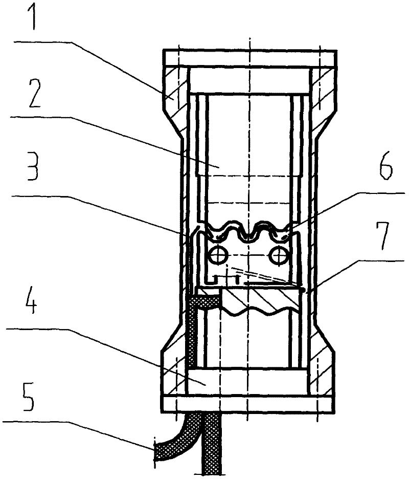
[0025] The sensor consists of three parts: an elastic element, a microbend and an optical fiber length compensation device.

[0026] Elastic elements can be divided into elastic support elements and elastic sensitive elements. Elastic support elements only play the role of force transmission and force, and their deformation is not included in the effective deformation. Elastic sensitive elements not only play the role of force transmission and force, but also their Deformation is an effective deformation. The latter is adopted in this design, and the sleeve 1 is used as an elastic sensitive element, which not only plays the role of force transmission and stress, but also its deformation is effective deformation.

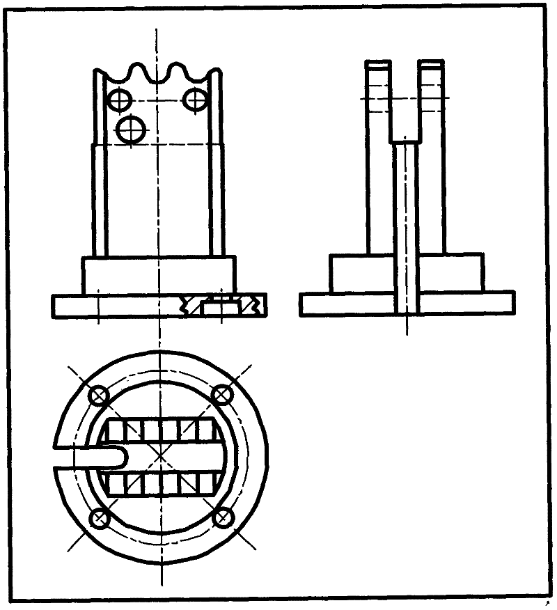
[0027] The microbender is composed of a microbender upper piece 2 and a microbender lower piece 4 . In order to ensure that the microbender can meet the requirements of a certain number of working teeth and not oversize, a double row of extrusion teeth is used to pa...


PUM


Abstract

The invention relates to an optical fibre sensor, which is used for measuring loading deformation conditions of objects, such as road bridges, long mechanical arms and the like by adopting a micro-bend light intensity modulation principle. A core part in the sensor is a micro-bend device, wherein the micro-bend device is in the form of non-uniform tooth tops and double rows of extrusion teeth; the non-uniform tooth tops can be used for avoiding breakage caused by stretching of a fibre core when the sensor is assembled and works; the double rows of extrusion teeth can be used for ensuring the number of effective teeth on the premise of not increasing the volume; therefore, the sensitivity of the sensor is ensured; the length compensation of an optical fibre is realized through a compensation spring device; and the integral assembly is ensured through a locating sheet. The sensor disclosed by the invention has the advantages of being simple in structure, low in volume, light in weight, strong in interference resistance capability, higher in measurement sensitivity, better in stability and low in cost.

Description

Technical field [0001] The invention relates to an optical fiber sensor used for measuring the loading and deformation conditions of objects such as road bridges and mechanical long arms. Background technique [0002] Today's society has entered the information age characterized by photoelectric technology and sensing technology. Optical fiber sensing technology represents the development trend of a new generation of sensors. It has the characteristics of high technical content, good economic benefits, strong penetration ability, and broad market prospects. For the attention of the world. [0003] Compared with traditional sensors, fiber optic sensors have the advantages of being free from electromagnetic field interference, safe signal transmission, non-contact measurement, high sensitivity, high precision, suitable for use in various harsh environments, non-destructive and easy to use. [0004] Today, my country's highway traffic is developing rapidly, and the number of r...

Claims


Application Information

Patent Timeline
Patent Type & Authority Applications(China)
IPC IPC(8): G01B11/16
Inventor 卢瑞文闵达
Owner GUANGZHOU NANYANG POLYTECHNIC
Learn More