Spring tube digital compression gauge based on Hall effect

A Hall effect, spring tube technology, applied in the direction of fluid pressure measurement involving magnet displacement, can solve the problems of high price and low cost performance, and achieve the effect of no mechanical wear, high cost performance, and improved grade accuracy

Inactive Publication Date: 2012-06-27
WUHAN UNIV OF TECH
View PDF5 Cites 4 Cited by
  • Summary
  • Abstract
  • Description
  • Claims
  • Application Information

AI Technical Summary

Problems solved by technology

At the same time, most of the current digital pressure gauge sensors use ceramic pressure sensors. The disadvantage is that the price is expensive. Compared with the same precision mechanical gauge, the price is several times or even dozens of times, and the cost performance is low.

Method used


Image

  • Spring tube digital compression gauge based on Hall effect
  • Spring tube digital compression gauge based on Hall effect
  • Spring tube digital compression gauge based on Hall effect

Examples


Embodiment Construction

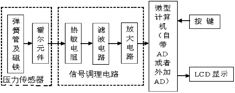
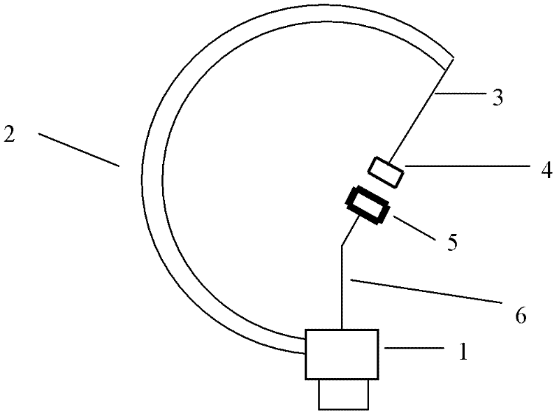
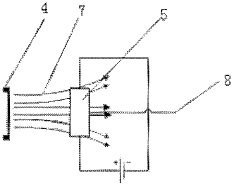
[0017] The principle diagram of a spring tube digital pressure gauge based on the Hall effect of the present invention is as follows figure 1 As shown, it includes a pressure sensing element, a signal conditioning circuit, a microcomputer, an analog-to-digital converter, a display screen, buttons, a power supply, and a connector; the pressure sensing element includes a spring tube 2, a magnet 4, and a Hall element 5 One end of the spring tube 2 is provided with a joint 1 connected to the pressure source, and the other end is closed as a free end; a magnet bracket 3 is connected to the closed end, and a magnet 4 is installed on it; the Hall element bracket is installed on the upper part of the joint 1 6. A Hall element 5 is installed on it; the sensing surface of the Hall element 5 faces and is close to the magnet 4; the output end of the Hall element is connected with the input end of the signal conditioning circuit, and the output end of the signal conditioning circuit is conn...


PUM


Abstract

The invention provides a spring tube digital compression gauge based on a Hall effect. The spring tube digital compression gauge comprises a pressure sensing element, a signal conditioning circuit, a microcomputer, an analog-to-digital converter, a display screen, a button, a power supply and a joint. The pressure sensing element comprises a spring tube, a magnet, and a Hall element. One end of the spring tube is provided with the joint which is connected with a pressure source, and the other end is enclosed as a free end. A blind end is connected with a magnet support which is installed with the magnet. An upper part of the joint is installed with a Hall element support which is installed with the Hall element. An induction surface of the Hall element directly faces the magnet and is close to the magnet. An output terminal of the Hall element is connected with an input terminal of the signal conditioning circuit. An output terminal of the signal conditioning circuit is connected with the microcomputer and the analog-to-digital converter. The microcomputer is connected with the display screen and the button. The pressure sensing element is installed in a shell of the gauge. A bottom of the spring tube is connected with the power supply. The compression gauge has auxiliary functions of unit switching, zero point calibration, non-linear compensation, temperature compensation and the like, precision is high, a life is long, a measuring range is large, and cost is low.

Description

technical field [0001] The invention relates to a spring tube digital pressure gauge based on Hall effect. Background technique [0002] Computer control technology has been widely used. At present, most of the instruments in the pressure gauge industry still use the pointer structure. Most of the structure of this pressure gauge is completed by the mechanical structure. The mechanical structure is easy to wear and the spring is easy to wear when it is used for a long time. Disadvantages such as loss of elasticity, difficulty in reading data, and difficulty in unit switching. According to the current social development, most industries are adopting computer intelligent control, and its intuitive interface and humanized design are more in line with people's needs. At the same time, most of the sensors of current digital pressure gauges use ceramic pressure sensors. The disadvantage is that they are expensive. Compared with mechanical gauges with the same precision, their pri...

Claims


Application Information

Patent Timeline
Patent Type & Authority Applications(China)
IPC IPC(8): G01L9/14
Inventor 熊和金
Owner WUHAN UNIV OF TECH
Why Eureka
Try Eureka