

Pressure fluctuation calibrating device of pressure or differential pressure sensor and calibrating method thereof
A pressure sensor and calibration device technology, applied in measurement devices, fluid pressure measurement, instruments, etc., can solve the problems of reducing friction coefficient, high cost, and high environmental requirements, and achieve high pressure measurement resolution, device cost reduction, and accuracy. Effects of pressure changes
- Summary
- Abstract
- Description
- Claims
- Application Information
AI Technical Summary
Problems solved by technology
Method used
Image

Examples
Embodiment 1
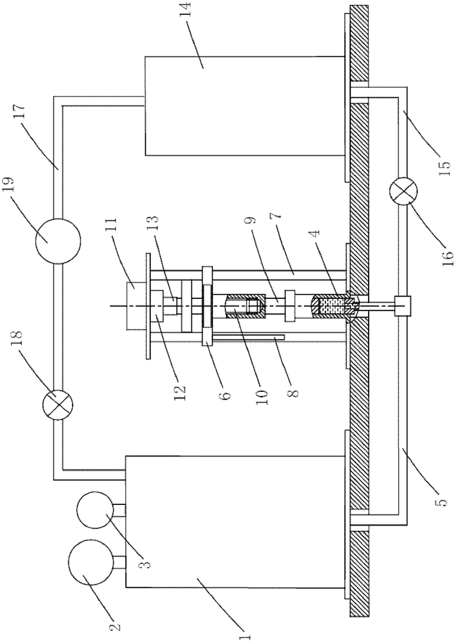
[0027] Example 1: see figure 1 , to calibrate the pressure fluctuation of the pressure sensor, the device includes:
[0028] The main pressure vessel 1 and the standard pressure sensor 2 connected to the main pressure vessel and the pressure sensor 3 to be calibrated;
[0029] The frame and the cylinder body 4 fixed on the frame, the bottom of the inner cavity of the cylinder body 4 communicates with the main pressure vessel 1 through the No. Between the seals, the piston moves up and down to drive the fluid level in the cylinder cavity to rise and fall, causing the fluid pressure in the main pressure vessel to fluctuate. The top outer wall of the piston rod 9 of the piston is fixed on a guide flange 6, and the guide flange 6 takes the column 7 of the frame as a guide rail, and is provided with a displacement sensor 8 on the guide flange, and the upper section of the piston rod 9 is hollow. And be provided with internal thread, the top of frame is provided with lead screw 10...
Embodiment 2
[0035] Embodiment 2: For the pressure fluctuation calibration of the differential pressure sensor, its device includes:
[0036] The main pressure vessel 1 and the standard pressure sensor 2 connected to the main pressure vessel and the pressure sensor 3 to be calibrated;
[0037] The frame and the cylinder body 4 fixed on the frame, the bottom of the inner cavity of the cylinder body 4 communicates with the main pressure vessel 1 through the No. Between the seals, the piston moves up and down to drive the fluid level in the cylinder cavity to rise and fall, causing the fluid pressure in the main pressure vessel to fluctuate. The top outer wall of the piston rod 9 of the piston is fixed on a guide flange 6, and the guide flange 6 takes the column 7 of the frame as a guide rail, and is provided with a displacement sensor 8 on the guide flange, and the upper section of the piston rod 9 is hollow. And be provided with internal thread, the top of frame is provided with lead screw...
PUM
 Abstract
Description
Claims
Application Information