Device and method for measuring all physical polarization parameters based on least square optimization

A technology of polarization parameters and least squares, applied in the direction of testing optical properties, etc., can solve problems such as the inability to derive direct analytical expressions of multiple parameters, and achieve the effect of direct measurement

Inactive Publication Date: 2012-06-27
SHANGHAI UNIV
View PDF3 Cites 10 Cited by
  • Summary
  • Abstract
  • Description
  • Claims
  • Application Information

AI Technical Summary

Problems solved by technology

Therefore, the test system generally requires strict polarization alignment calibration; and it is feasible when the measured parameters ar

Method used


Image

  • Device and method for measuring all physical polarization parameters based on least square optimization
  • Device and method for measuring all physical polarization parameters based on least square optimization
  • Device and method for measuring all physical polarization parameters based on least square optimization

Examples


Embodiment 2

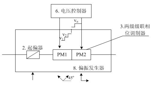
[0097] Embodiment two: the present embodiment is basically the same as embodiment one, and the special feature is: see Image 6 . Image 6 It is a system schematic diagram of the full polarization parameters of the optical device between any two points in the test system of the present invention. The test is carried out in three steps. First, the polarization generator 8 is placed at the position C of the polarization analyzer, that is, the output end of the system, and the output polarization state of the polarization generator corresponding to a set of control voltages is measured by the polarization analyzer ;Secondly, insert the polarization generator into the output point B of the subsystem under test, and measure the polarization state of the system output corresponding to the same group of control voltages by the polarization analyzer ; Finally, insert the polarization generator into point A of the input terminal of the measured subsystem, and then correspond to t...

Embodiment 3

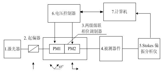
[0103] Embodiment 3: This embodiment is basically the same as Embodiment 1, and the special features are: see figure 1 . Will figure 1 The light source in is replaced by a wavelength tunable light source to test the spectral characteristics of the device polarization conversion parameters. First, under the same set of control voltages, the adjustable light source emits light of different wavelengths into the device under test (4), and finally the polarization state parameter of the output light is recorded by the polarization analyzer. The polarization state at m wavelengths , and then place the polarization generator at the input end of the device under test. Under the same set of control voltage conditions as before, the adjustable light source is on the same m wavelengths, and the polarization analyzer records the polarization at the output end of the device under test. state , from which the following formula can be established:

[0104] (18)

[01...


PUM


Abstract

The invention relates to a device and a method for measuring all physical polarization parameters based on least square optimization. The device consists of a laser, a polarizer, a two-stage cascaded phase modulator, a device to be measured and a polarization analyzer. The method comprises the following steps that: light generated by the laser passes through the polarizer, linearly polarized light is output and enters the two-stage cascaded phase modulator, the output of the modulator directly enters the polarization analyzer or enters the polarization analyzer via the device to be measured, and the polarization analyzer measures Stokes parameters in input and output light polarization states of the device to be measured under the two conditions, which correspond to the same group of photoelectric modulator modulated voltages; a system equation set which comprises all 16 physical parameters for describing the polarization properties of the device is established according to a relationship between the input and output polarization states of the device to be measured and a Mueller matrix for reflecting the depolarization characteristic, polarization dependent loss characteristic and double refraction characteristic of the device to be measured; and the equation set is subjected to numerical solution by a least square method, and the 16 solved physical polarization parameters can be obtained through optimization.

Description

technical field [0001] The invention relates to a method for measuring all physical polarization parameters of an optical device in an optical fiber system. In particular, it relates to a measurement device and method for all physical polarization parameters based on least squares optimization, and uses a Stokes polarization analyzer to realize the measurement of all physical polarization parameters of an optical device. Background technique [0002] In optical communication, sensing, and measurement systems, the polarization conversion characteristics of various photonic devices and subsystems directly affect the performance of the system. Therefore, detecting the polarization conversion characteristics of any part of the system or device in various optical systems is the key to achieving high performance. One of the keys to optical communication, optical sensing and measurement systems. [0003] In addition, during the research and development of materials science, the po...

Claims


Application Information

Patent Timeline
IPC IPC(8): G01M11/02
Inventor 王春华李力黄肇明刘涛何星剑
Owner SHANGHAI UNIV
Why Eureka
Try Eureka