
Method and system for detecting lane marked lines

A lane line detection and lane line technology, applied in the field of lane line detection, can solve the problems of low precision, wide fluctuation range, complex environment, etc., and achieve the effect of stable operation and good fault tolerance

Inactive Publication Date: 2012-06-27
深圳市宝捷信科技有限公司
View PDF4 Cites 37 Cited by
  • Summary
  • Abstract
  • Description
  • Claims
  • Application Information

AI Technical Summary

Problems solved by technology

In the pictures taken by the car camera, affected by the light and the shadow of the object, the gray level of the road itself usually fluctuates widely, and the effect of gray level segmentation has a large error
The Hough transform directly obtains the lane line also has the following disadvantages: 1) The surrounding environment of the road is complex and there are often linear objects such as utility poles and street light poles, which easily lead to false detection; 2) Double yellow lines in the road, virtual and real double White lines, road marking lines, etc., are often mistaken for the dividing line of the current lane; 3) The actual road dividing line is often not an ideal straight line, and the accuracy of directly treating the straight line as the final lane line is not high; it can be seen that, This method does not work well in practice

Method used


Image

  • Method and system for detecting lane marked lines
  • Method and system for detecting lane marked lines
  • Method and system for detecting lane marked lines

Examples


Embodiment 1

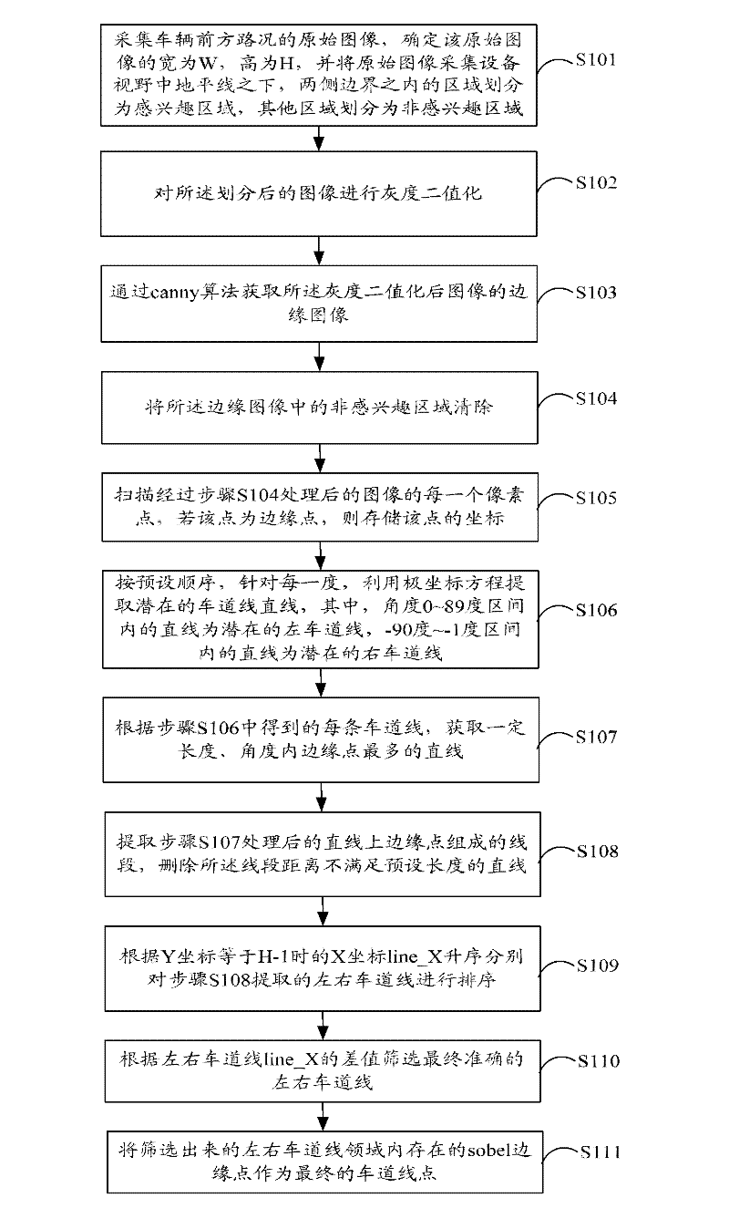
[0040] figure 1 The implementation flow of the lane line detection method provided by Embodiment 1 of the present invention is shown, and the process of the method is described in detail as follows:

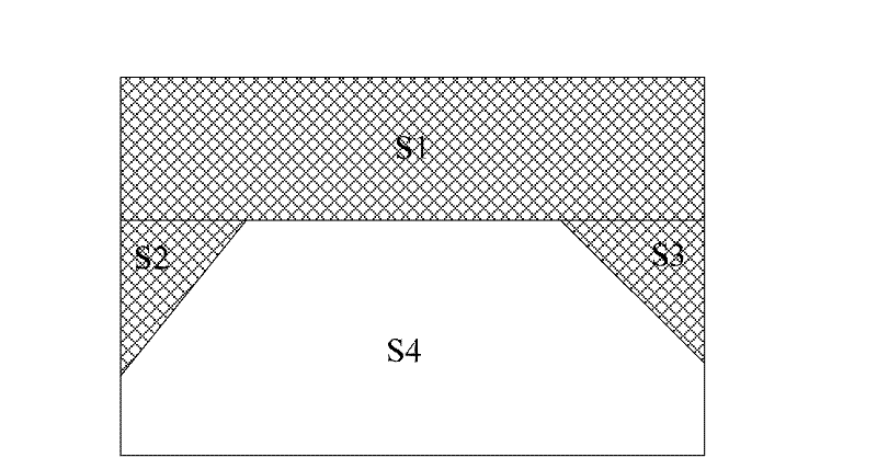
[0041] In step S101, the original image of the road condition in front of the vehicle is collected, the width of the original image is determined to be W, and the height is H, and the area under the horizon line in the field of view of the original image acquisition device and within the borders on both sides is divided into areas of interest region, and other regions are classified as non-interest regions.

[0042] In this embodiment, the original image in front of the vehicle is collected by an image acquisition device (such as a camera) installed on the vehicle, and the image acquisition device is set with internal parameters and external parameters. Wherein, the internal parameters include principal point coordinates, effective focal length, etc., and the external parameters...

Embodiment 2

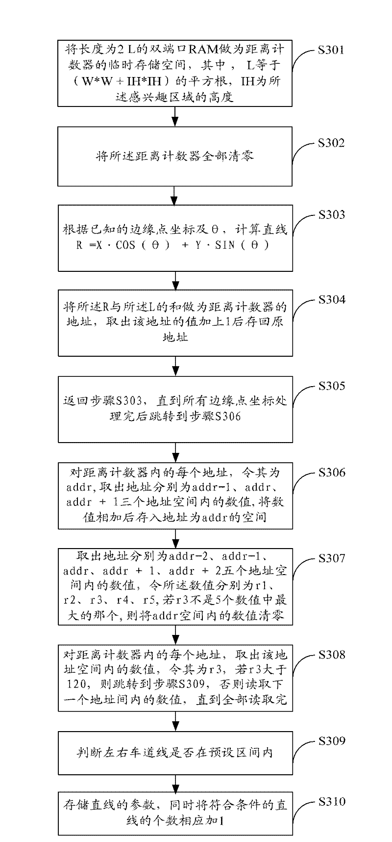
[0059] image 3 The specific flow of the straight line calculation provided by Embodiment 2 of the present invention is shown, and the process is described in detail as follows:

[0060] In step S301, the dual-port RAM with a length of 2L is used as the temporary storage space of the distance counter, wherein IH is the height of the region of interest.

[0061] In this example, let Because among all straight lines passing through any point in the region of interest, the minimum R is -L and the maximum is L, so the length is L 2 The dual-port RAM is used as a temporary storage space for the distance counter.

[0062] In step S302, all the distance counters are cleared.

[0063] In step S303, according to the stored edge point coordinates, calculate R=X cos(θ)+Ysin(θ), where θ is the angle between the vertical line and the horizontal line from the pole to the straight line.

[0064] In this embodiment, when X, Y, and θ are known, the straight line R is calculated accordin...

Embodiment 3

[0075] Figure 4 The specific flow of straight line selection provided by Embodiment 3 of the present invention is shown, and the process is described in detail as follows:

[0076] In step S401, each extracted straight line is processed in the order of [0°, 89°][-90°, -1°], and the parameters R1, θ1, S1, line_x1 of the currently processed straight line are obtained, if described If the parameters are all zero, then take the next straight line for processing, otherwise skip to step S402.

[0077] In step S402, scan the coordinates (X, Y) of each edge point sequentially according to the storage order, and calculate R according to R=Xcos(θ)+Ysin(θ), where θ=θ1, if the absolute value of R-R1 is less than 3 , the point is considered to be on the straight line, and the coordinates of the point are stored in the temporary memory, otherwise they are not stored;

[0078] In step S403, scan the temporary memory according to the storage order, if the distance between two points before...


PUM


Abstract

The invention is suitable for the technical field of intelligent traffic and provides a method and a system for detecting lane marked lines. The method comprises the following steps of: obtaining an input original image and performing binaryzation on gray level of the input original image; utilizing a canny algorithm to obtain an edge image of the image after being subjected to gray level binaryzation; removing non-interesting area in the edge image; scanning each pixel point of the image after being processed; if the point is an edge point, storing the coordinate of the point; taking a straight line for each degree, thereby obtaining initial left and right lane marked lines; taking the straight line meeting a first preset condition and having the most edge points according to the initialleft and right lane marked lines; taking the left and right lane marked lines meeting a second preset condition; sequencing the taken left and right lane marked lines; screening out the final left and right lane marked lines according to a line_X difference of the left and right lane marked lines; and taking the sobe1 edge points in adjacent areas of the screened left and right lane marked lines as the final accurate lane marked line points. According to the method provided by the invention, the speed and the precision of detecting the lane marked lines can be efficiently increased.

Description

technical field [0001] The invention belongs to the technical field of intelligent transportation, and in particular relates to a method and system for lane line detection. Background technique [0002] Lane line detection is a basic and necessary function in the assisted driving system of intelligent vehicles. It is the prerequisite for vehicle separation in the current lane, automatic driving, and lane departure warning. [0003] The existing lane line detection technology generally uses a digital signal processor (DSP) chip to operate on the acquired image, and directly obtains the lane line through grayscale segmentation or Hough transform. In the pictures taken by the car camera, affected by the light and the shadow of the object, the gray level of the road itself usually fluctuates widely, and the effect of gray level segmentation has a large error. The Hough transform directly obtains the lane line also has the following disadvantages: 1) The surrounding environment ...

Claims


Application Information

Patent Timeline
IPC IPC(8): G06K9/46G06K9/60G08G1/00
Inventor 梁火炎李耀华李运秀梁日雄彭青峰余加波李佐广
Owner 深圳市宝捷信科技有限公司
Learn More